Transceiver Toolbox
Note
This section only gives an overview on the Transceiver Toolbox, for all details, see the dedicated doc.
Analog Devices Transceiver Toolbox For MATLAB and Simulink is a set of tools to model, interface, and target with ADI transceiver devices within MATLAB and Simulink. These are combined into a single Toolbox which contains a set of Board Support Packages (BSP). The list of supported boards is provided below.
Quick Start with Toolbox
The current stable Toolbox can be downloaded from the ADI Transceiver Toolbox repository (releases). Download the latest mltbx file then open that file within MATLAB. Opening the file will automatically install the Toolbox, adding the necessary components to your MATLAB path. The “Analog Devices, Inc. Transceiver Toolbox” will appear in your Add-Ons Explorer within MATLAB.
To interface and stream data with hardware will require installation of Libiio and one of two Hardware Support Packages from MathWorks. The libiio library can be obtained from the ADI libiio repository.
Libiio Installers
Download
Stable releases are available at ADI libiio repository (releases).
These support packages provide the necessary libIIO MATLAB bindings used by ADI’s system objects. Starting in R2024a, the functionality of Communications Toolbox Support Package for Xilinx Zynq-Based Radio is included in SoC Blockset Support Package for AMD Devices.
Download
Toolbox Dependencies
Depending on your needs, different toolboxes will be required. For basic data streaming into MATLAB or Simulink only the following MathWorks toolboxes are required:
For HDL code generation the following are required:
Specific demos may require other toolboxes:
Models of different transceivers may require different toolboxes as well. More information can be found at the RF Blockset Model of AD9361 from MathWorks page.
API Documentation
Building the Toolbox Manually
The toolbox can only be built under Linux or with Cygwin on a Windows platform. Conveniently, the entire process is automated with a Makefile located in the CI/scripts folder of the repository. The following is required on the system before the build process can be run:
A supported MATLAB version installed in the default location (/usr/local/MATLAB)
A supported Vivado version installed in the default location (/opt/Xilinx)
Packages: git zip unzip tar make wget sed
Warning
You should only manually build the toolbox if you require a custom branch or no toolbox installer is available
First clone the repo and move into it:
~$
git clone https://github.com/analogdevicesinc/TransceiverToolbox.git \
     --recurse-submodules
~$
cd TransceiverToolbox
To build the toolbox run the following:
~/TransceiverToolbox$
make -C CI/scripts build
Add the application libraries for AD936X based devices if desired
~/TransceiverToolbox$
make -C CI/scripts add_libad9361
To create an installable tlbx file run:
~/TransceiverToolbox$
make -C CI/scripts gen_tlbx
Running Integrated HDL Tests
This process assumes the toolbox has been built. To run tests for a specific carrier run the test target with the carrier name like so:
~/TransceiverToolbox$
make -C CI/scripts test BOARD=zed
Without specifying the carrier all tests will run (This takes a long time!):
~/TransceiverToolbox$
make -C CI/scripts test
Device Control and Data Streaming
Device interfaces which provide control and data streaming are implemented with MATLAB System Objects and Simulink Blocks. These System Objects can be accessed under the “adi” namespace in MATLAB and are followed by their part number or board name and finally Tx or Rx:
adi.<Part or Board Name>.<Tx or Rx>
For example, to instantiate an AD9361 object to control the Tx aspects of the transceiver it can be created as follows:
tx = adi.AD9361.Tx;
All supported boards are derived from low level objects based on their parts. For example, the DAQ2 Evaluation board actually contains an AD9680 and AD9144. Therefore, it simply uses AD9680 and AD9144 objects under the hood. However, to interact with the more familiar DAQ2 interface naming the Rx side can be instantiated like above as:
rx = adi.DAQ2.Rx;
For example usage of certain objects, it can be useful to inspect their related
test code which exercises initiations in different configurations. The available
code is available in the GitHub repo folder
here,
where object tests have the naming convention <Object>Tests.m.
To get a list of currently available objects with the BSP installed simply run:
help adi
To get more information on a given object run:
help adi.<Part or Board Name>.<Tx or Rx>
or
doc adi.<Part or Board Name>.<Tx or Rx>
Common Attributes
There are some common attributes that need to be set for system objects and parts.
uriContext address of IIO device. Possible options include:IP with usage ‘’rx.uri = ‘ip:192.168.2.1’ ‘’
USB with usage ‘’rx.uri = ‘usb:1.2.3’ ‘’
Extending Interfaces
If a driver attribute or setting is not available in the standard objects it can be easily extended to cover more IIO attributes. See Extending Device Interfaces.
HDL Targeting with HDL-Coder
Targeting is code generation that translates a designated MATLAB or Simulink subsystem to HDL code and creates a custom bitstream for the FPGA fabric. This custom bitstream is then downloaded to the FPGA on the development board. By moving part or all of your algorithm to the hardware, you speed up signal processing.
The Analog Devices Toolbox for MathWorks HDL Workflow Advisor is a collection of board definitions and reference designs that provide to the MathWorks HDL Workflow Advisor support to:
Generate IP blocks compatible with Analog Devices HDL reference designs for various Analog Devices platforms
Automatically insert the generated IPs into the Analog Devices Vivado HDL reference designs
This Analog Devices Toolbox is based on the MathWorks Board and Reference Design Registration System.
Functionality
The MathWorks HDL Workflow Advisor
enables users to automatically generate HDL code from a Simulink model. The user
can choose from a selection of several different Target Workflows, including
ASIC/FPGA, FPGA-In-The-Loop, and IP Core Generation. Target Platform
selections include Xilinx Evaluation Boards and Altera Evaluation Boards as well
as other custom evaluation boards.
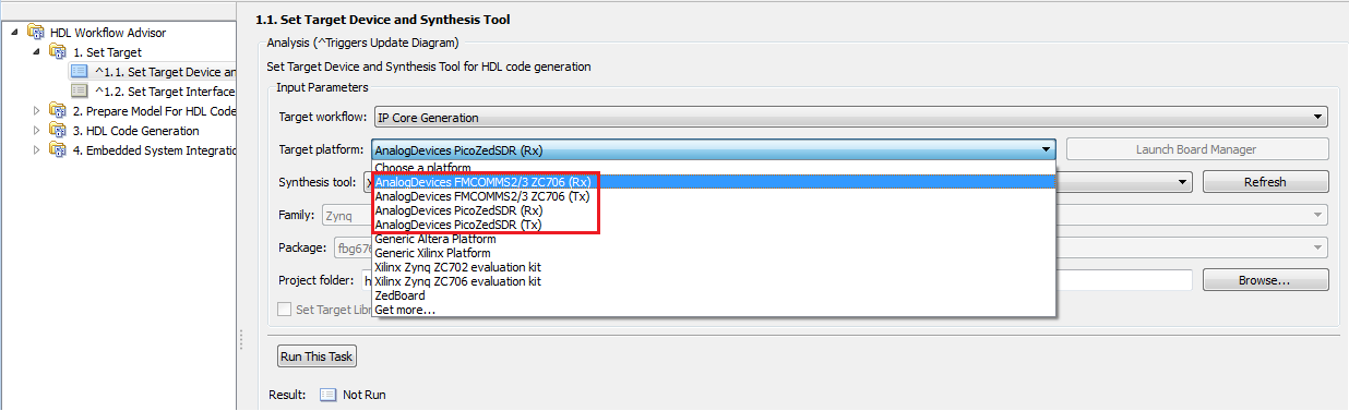
The Analog Devices BSP for HDL Workflow Advisor extends the set of Target Workflows for IP Core Generation with the Analog Devices boards listed in the Supported Platforms section. The BSP consists of a set of board definitions that specify all the characteristics needed by the HDL Workflow Advisor to be able to incorporate a board in the code generation flow, as well as a set of Xilinx Vivado reference designs that are used by the Workflow Advisor to automatically insert the generated IPs into the Vivado designs. All the Analog Devices Vivado HDL reference designs have inside a ‘donut hole’ to accommodate custom IPs. Each design exposes a set of interface signals to which the IP can connect to. All these signals are specified in the board definition and are available in the Workflow Advisor GUI to connect to the generated IP’s ports.
When running the Workflow Advisor the first step if to select the Target Platform. The figure below shows some of the available Analog Devices target platforms.
The next step is to configure the interfaces between the IP and the reference design. Each target platform has a set of interface signals that are accessible in the Target Platform Interfaces drop down boxes from step 1.2 (Set Target Interface) of the HDL Workflow Advisor. The figure below shows an example of how to configure the target interface for a specific model.
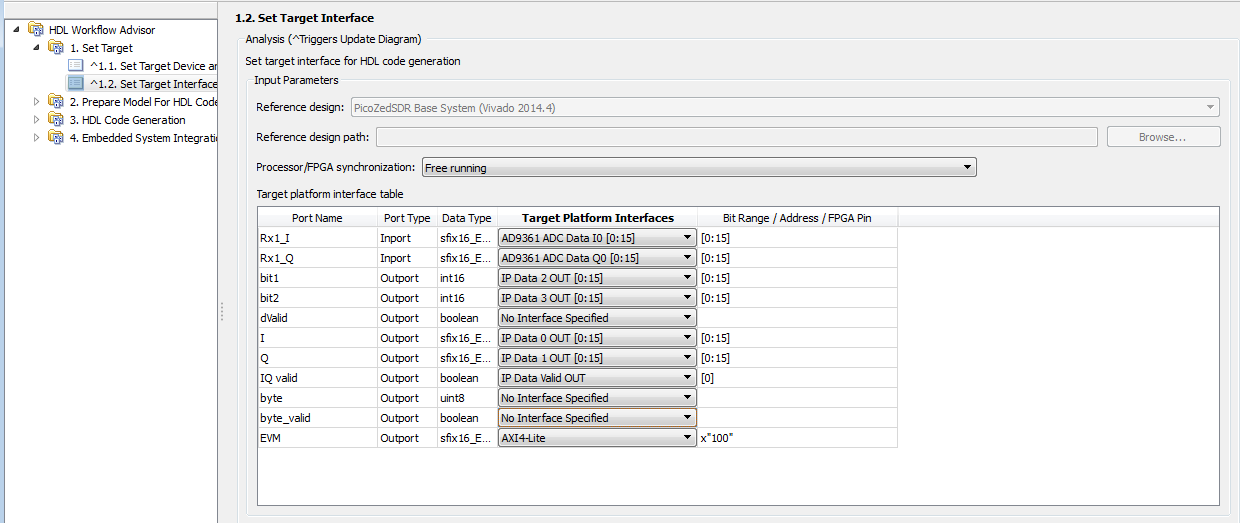
All the Analog Devices AD9361 based SDR platforms have the same interface signals and they are dependent on the type of flow that is selected – receive (Rx) or transmit (Tx). The table below describes the interface signals for the AD9361 based SDR platforms.
Receive flow (Rx)
Signal name |
Width |
Description |
|---|---|---|
IP Data 0 OUT |
16 |
Custom IP data output signal. This signal is connected to a DMA channel in the ADI reference design. |
IP Data 1 OUT |
16 |
Custom IP data output signal. This signal is connected to a DMA channel in the ADI reference design. |
IP Data 2 OUT |
16 |
Custom IP data output signal. This signal is connected to a DMA channel in the ADI reference design. |
IP Data 3 OUT |
16 |
Custom IP data output signal. This signal is connected to a DMA channel in the ADI reference design. |
IP Data Valid OUT |
1 |
Data valid signal from the custom IP. Used to signal to the rest of the design that the IP data out channels have valid data. The duration must be 1 clock cycle. |
AD9361 ADC Data I0 |
16 |
AD9361 ADC I0 channel data. |
AD9361 ADC Data Q0 |
16 |
AD9361 ADC Q0 channel data. |
AD9361 ADC Data I1 |
16 |
AD9361 ADC I1 channel data. |
AD9361 ADC Data Q1 |
16 |
AD9361 ADC Q1 channel data. |
Transmit flow (Tx)
Interface signal name |
Width |
Description |
|---|---|---|
IP Data 0 IN |
16 |
Custom IP data input signal. This signal is connected to a DMA channel in the ADI reference design. |
IP Data 1 IN |
16 |
Custom IP data input signal. This signal is connected to a DMA channel in the ADI reference design. |
IP Data 2 IN |
16 |
Custom IP data input signal. This signal is connected to a DMA channel in the ADI reference design. |
IP Data 3 IN |
16 |
Custom IP data input signal. This signal is connected to a DMA channel in the ADI reference design. |
IP Load Tx Data OUT |
1 |
Custom IP output signal used to notify the design that the IP is ready to receive new input data. The duration must be 1 clock cycle. |
AD9361 DAC Data I0 |
16 |
AD9361 DAC I0 channel data. To be used as input into the custom IP. |
AD9361 DAC Data Q0 |
16 |
AD9361 DAC I0 channel data. To be used as input into the custom IP. |
AD9361 DAC Data I1 |
16 |
AD9361 DAC I0 channel data. To be used as input into the custom IP. |
AD9361 DAC Data Q1 |
16 |
AD9361 DAC I0 channel data. To be used as input into the custom IP. |
The custom IP always runs at the sample clock and must be able to process / generate a sample every clock cycle.
Once the target interface has been defined, make sure to select the “Target Language” as Verilog (defaults to VHDL) in Step 3.1.1 of the HDL Workflow Advisor. All the other settings of steps 2 and 3 of the HDL Workflow Advisor can be left in their default state and the project generation process can be started by running step 4.1 (Create Project). The result of this step is a Vivado project which has the custom IP core integrated into the Analog Devices HDL reference design. The bitstream for the design can be generated either by running step 4.4 (Create bitstream) or by compiling the generated Vivado Project directly in Vivado. The project can be found in the hdl_prj/vivado_ip_prj folder.
Further Reading
Four Quick Steps to Production: Using Model-Based Design for Software-Defined Radio - Part 4
Creating a BOOT.BIN from HDL Workflow Advisor
Unlike the support package provided by MathWorks, the update process for the bitstreams requires creation of a BOOT.BIN file which will be compatible with the ADI SD card.
First make sure you have a valid SD card for your platform with the necessary devicetree and kernel image selected. See Kuiper documentation for more information about configuring the SD card with a Kuiper Linux image.
Once your SD card is ready, in step 4.3 “Build FPGA Bitstream” of HDL Workflow Advisor select a custom Tcl file for synthesis build. Utilize this adi_build.tcl file located within the BSP as your custom tcl file.
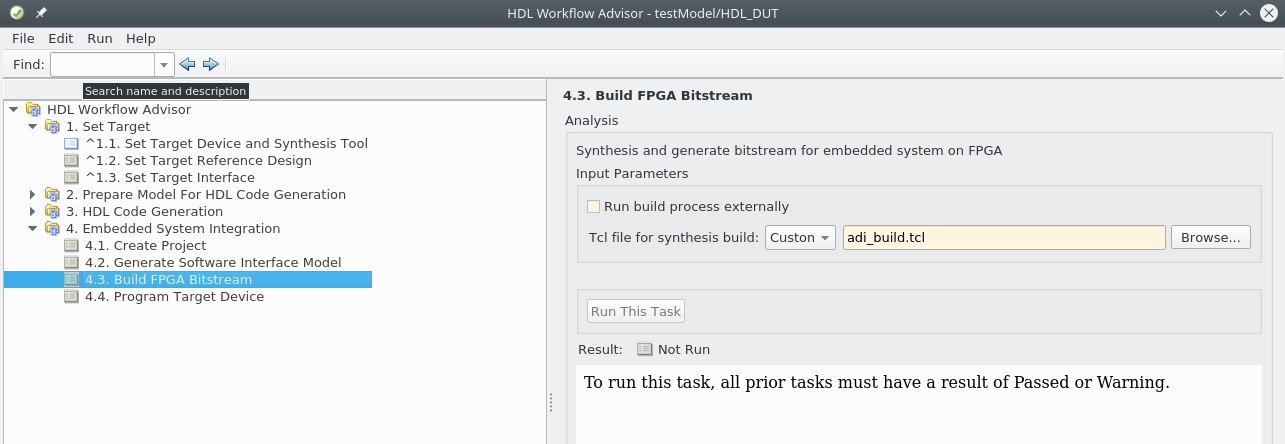
Once the bitstream is built it will generate the BOOT.BIN necessary for booting your system. Place the generated BOOT.BIN in the root of your ADI SD card’s BOOT partition.
Simulation Models of Hardware
Models are typically used primarily in simulation only types of environments
(they don’t include any connection to hardware at all). Models can include many
different aspects of devices:
analog impairments (internal PLLs, mixers, LNA, gain stages, etc),
baseband impairments (ADC/DAC noise shaping, quantization, noise)
Digital Signal Processing impairments (the fixed and programmable DSP in the parts, quantization, overflow, latency, filtering, etc).
Some models may include all three aspects, some may only include one. It’s very common that as the model is of higher fidelity (includes more impairments, more details to be modeled) it runs slower. The fidelity vs simulation speed is always traded off by the model developer.
Some models are “complete” models, were developed and maintained by MathWorks, outside of ADI’s transceiver toolbox:
Supported Boards
The following have device-specific implementations in MATLAB and Simulink. If a device has an IIO driver, MATLAB support is possible, but a device-specific MATLAB or Simulink interface may not exist yet.
Evaluation Card |
FPGA Board |
Streaming Support |
Targeting |
Variants and Minimum Supported Release |
|---|---|---|---|---|
Pluto |
Yes |
Yes |
ADI (2018b) MathWorks (2017a) |
|
FMComms2/3/4 |
Zedboard |
Yes |
Yes |
ADI (2018b) MathWorks (2014b) |
ZC702 |
Yes |
Yes |
ADI (2018b) MathWorks (2014b) |
|
ZC706 |
Yes |
Yes |
ADI (2018b) MathWorks (2014b) |
|
ZCU102 |
Yes |
Yes |
ADI (2018b) MathWorks (2014b) |
|
FMComms5 |
ZCU102 |
Yes |
No |
ADI (2018b) MathWorks (2014b) |
ZC702 |
Yes |
Yes |
ADI (2018b) MathWorks (2014b) |
|
ZC706 |
Yes |
Yes |
ADI (2018b) MathWorks (2014b) |
|
ARRADIO |
Arrow SoCKit |
Yes |
No |
ADI (2018b) |
ADRV9361-Z7035 |
Yes |
Yes |
ADI (2018b) MathWorks (2015b) |
|
ADRV9364-Z7020 |
Yes |
Yes |
ADI (2018b) |
|
ADRV9371/5 |
ZC706 |
Yes |
Yes |
ADI (2018b) |
ZCU102 |
Yes |
Yes |
ADI (2018b) |
|
ZYNQ3 |
Yes |
No |
ADI (2018b) |
|
ADRV9002 |
ZCU102 |
Yes |
Yes |
ADI (2020a) |
ADRV9009/8 |
ZC706 |
Yes |
Yes |
ADI (2018b) |
ZCU102 |
Yes |
Yes |
ADI (2018b) |
|
Jupiter |
Yes |
No |
ADI (2020a) |
|
ADRV9009-ZU11EG |
Yes |
No |
ADI (2020a) |
|
FMComms8 |
ZCU102 |
Yes |
Yes |
ADI (2021a) |
Examples
Examples for streaming data and targeting FPGAs are listed within the Toolbox documentation itself. To view run the following with MATLAB:
doc adi
They can also be viewed on GitHub:
Highlighted demos:
Help & Support
Questions? Ask Help & Support.
Common Issues
libad9361-iio pathing error:
Error using loadlibrary
Could not find file ad9361-wrapper.h.
Error in loadlibrary
Error in adi.AD9361.Base/setupLibad9361 (line 111)
                [~, ~] = loadlibrary(libName, loadlibraryArgs{:});
Error in adi.AD9361.Rx/setupInit (line 281)
            setupLibad9361(obj);
Error in adi.common.RxTx/configureChanBuffers (line 226)
            setupInit(obj);
Error in matlabshared.libiio.base/setupImpl
Error in adi.common.RxTx/setupImpl (line 124)
            setupImpl@matlabshared.libiio.base(obj);
This error occurs when libad9361-iio is not on the MATLAB path. To fix it run the following within MATLAB:
A = adi.utils.libad9361
A.download_libad9361