Embedded Baremetal
Introduction
This workshop is designed to explore the fascinating world of baremetal programming, where you’ll learn to operate software that runs directly on the hardware. We’ll start by understanding what baremetal programming is and why it’s important. Through interactive demonstrations and hands-on activities, you’ll gain practical experience and see how these concepts apply to real-world projects. Let’s dive in and start our journey into the world of embedded systems!
Slide Deck and Booklet
Since this tutorial is also designed to be presented as a live, hands-on workshop, a slide deck is provided here:
Download
A complete booklet of the hands-on activity is also provided, as a companion to following the tutorial yourself:
Download
Theory
Baremetal Background
Traditionally, industry chip manufacturers would sell ICs without accompanying software:
Chip
Datasheet
Pseudocode with an initialization sequence and/or sequence of data acquisition
Complex parts require complex software.
ICs are everywhere.
ADI addressed this issue and started providing software for its parts as well.
There is a market advantage in selling parts with accompanying software.
Baremetal projects deliverables 10 years ago consisted of:
A .zip file containing the driver files
A .zip file containing a project
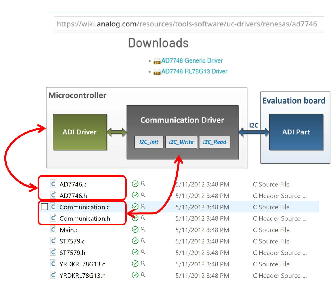
What ADI tried to do back then was to write an ADI driver for an ADI part, provided that we were selling the evaluation board with ADI part on it. The communication driver would be specific for each microcontroller or system board we would use: Maxim, Microchip, STM, etc. The structure was consisted mainly of buffers instantiations and function calls. The users would have to fill-in the code with their specific functions.
The initial approach had two targets:
Provide bare-metal ADI drivers for ADI parts to users
Leverage the driver code in a reference project running on hardware
Advantages
Driver code was MCU independent
Disadvantages
Customer responsibility to port reference project on a different MCU
.zip file distribution led to no version control and code duplication
Evolution provided
Provide a way for reference projects to run on multiple hardware combinations
Provide a build system that generates binaries and run them on hardware
Expose parts as IIO devices to PC applications
Improve code quality
What is No-OS
A software framework for embedded bare-metal development
Open-source
ADI-BSD license
Free
Large collection of platform agnostic device drivers for ADI parts
Significant collection of reference projects leveraging ADI evaluation boards
Reference projects can run on a wide range of hardware
Provides IIO enabled devices, making them accessible to PC applications that use libiio
What is a No-OS device driver
A No-OS device driver provides the software interface for hardware devices. Software application can access hardware functionality without knowing in detail how the driver operates. The register map, bit fields, are directly handled by the driver, as well as communication interface specific sequences and timings.
A piece of code implemented in C, in a .c and .h pair, stored in drivers/
Its programming interface is directly called by the application code
Defines its own descriptor structures and init_param
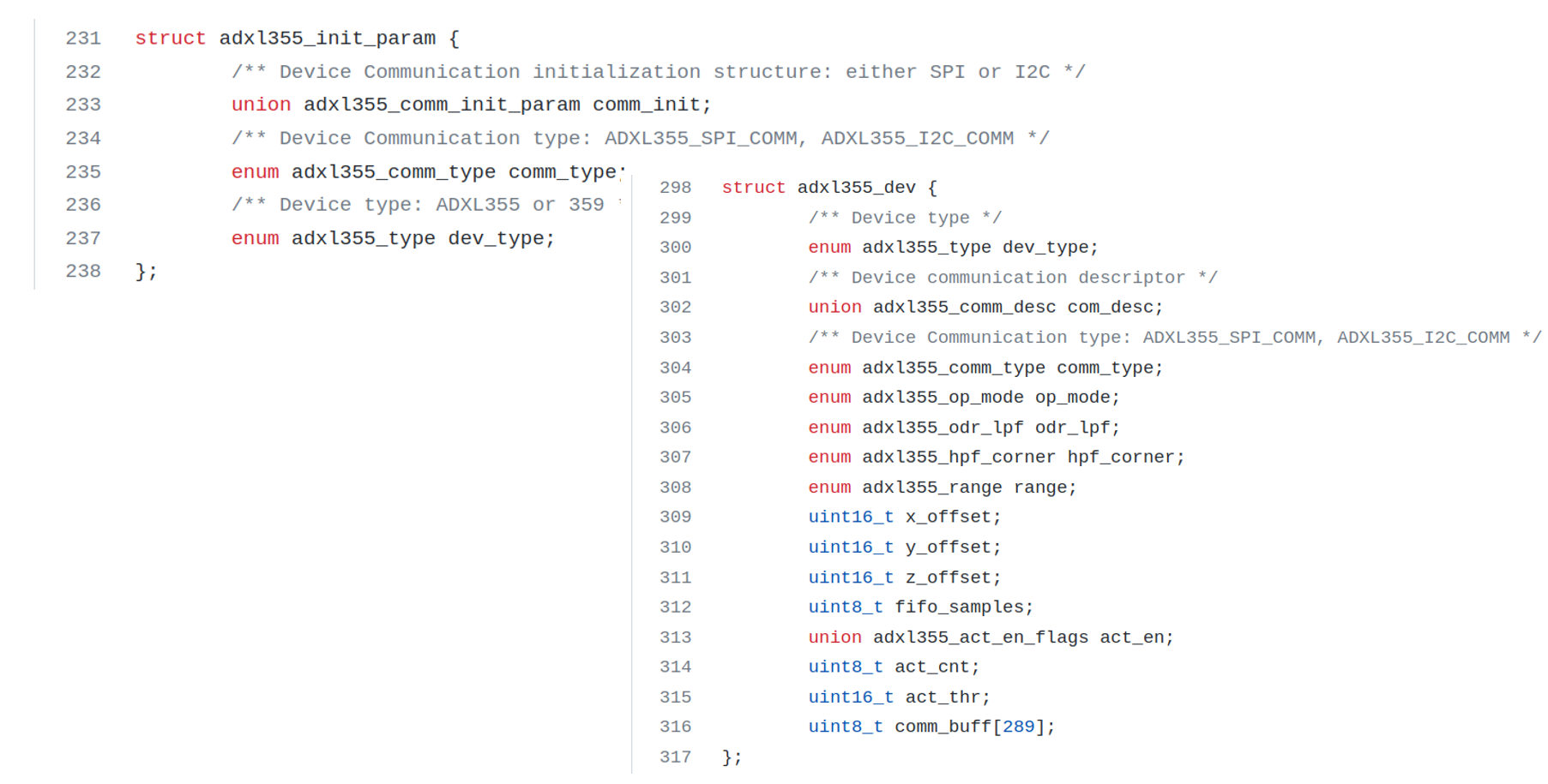
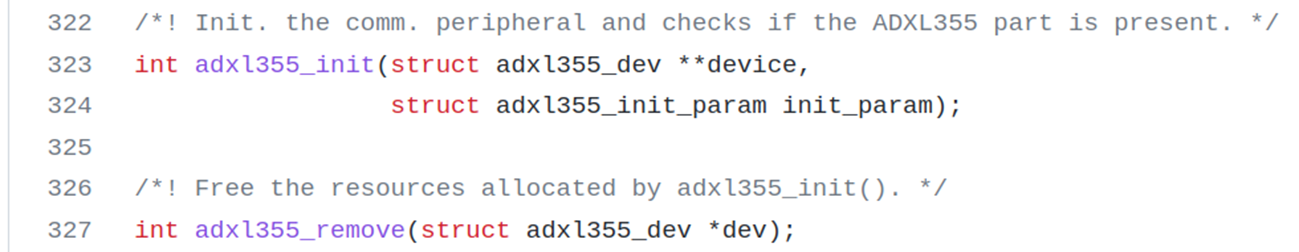
Contains minimum init() and remove() functions - take as parameter the specific init_param structure
Puts the devide into the desired state
Allocates memory
Provides the descriptor for being called in other driver function calls, the remove functions frees the resources allocated by the init()
Performs no-OS API calls, does not perform platform specific function calls, it’s platform agnostic
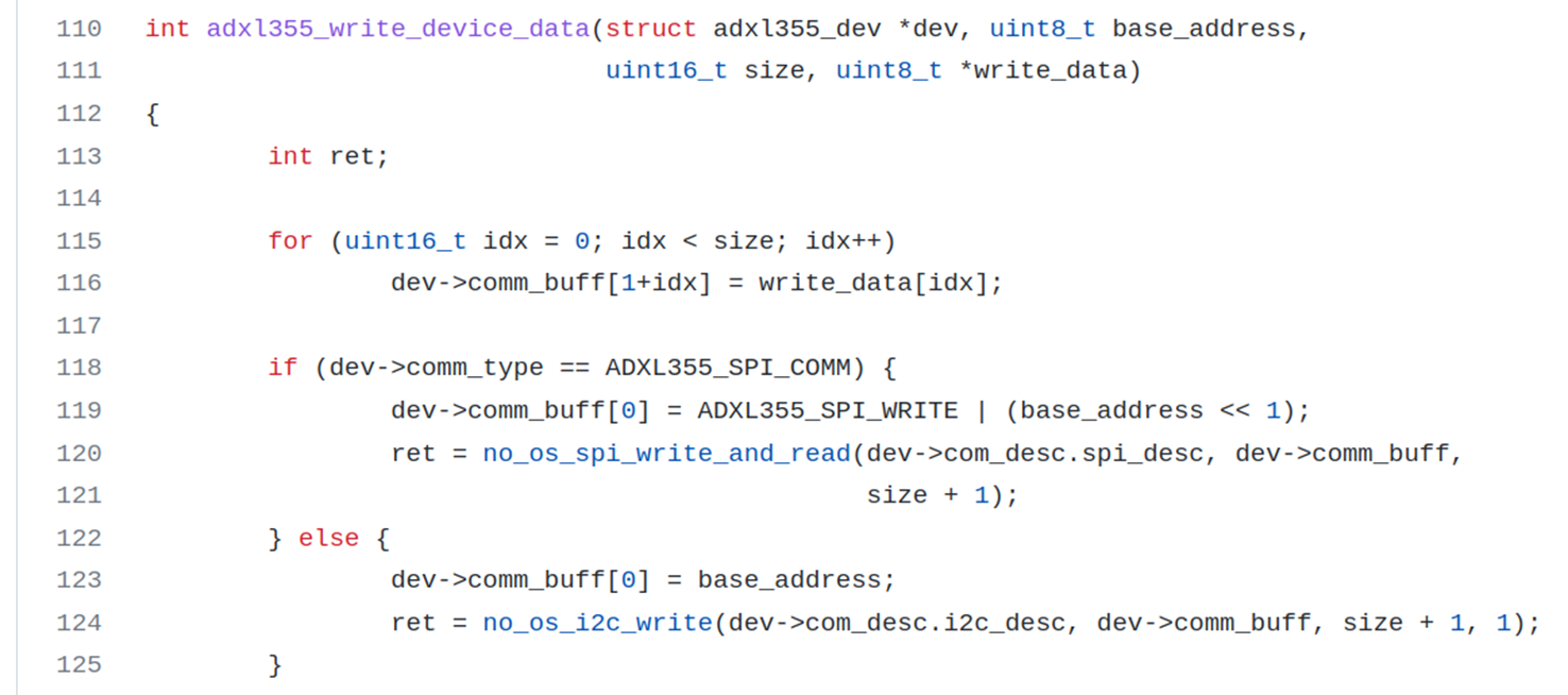
Software application can access hardware functionality without knowing in detail how the device operates
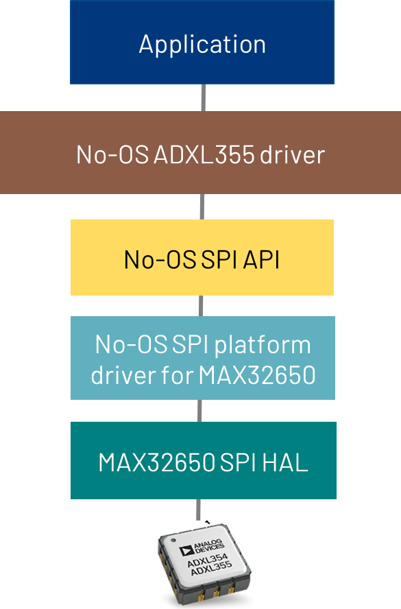
No-OS Platforms
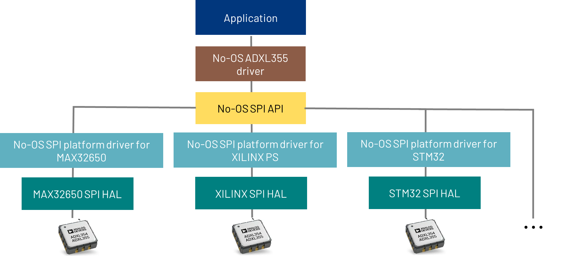
Platform drivers - represent an implementation of peripheral related no-OS API on a specific platform. Platform drivers use vendor HAL - Hardware Abstraction Layer. No-OS platform drivers are implementations of peripheral no-OS API on a particular platform.
No-OS modularity allow it to run a lot of its code on different platforms like:
Xilinx (Zynq7000, ZynqMP, Microblaze)
Maxim (32650, 32655, 32660, 32670, 78000), ADuCM (3029)
STM32 (almost any)
RaspberryPi Pico
Mbed
No-OS Projects
A project is basically an application that can be built, run and debugged on hardware
Specifications:
Located under projects/
It has a main() function
It uses drivers/ and drivers/platforms directories
It uses no-OS API
It uses various libraries
User interaction – serial, iio-oscilloscope
makefiles
Project hardware typically is made of:
An evaluation board
A carrier board
No-OS projects are used for:
ADI parts evaluation
Starting development based on a no-OS project
IIO Concepts
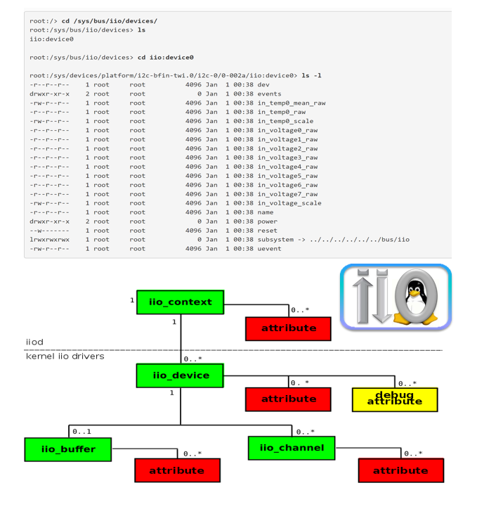
What is IIO - is a framework in the Linux kernel designed for devices such as adcs, dacs, etc.. There is a tree concept inside kernel, there is the context concept which is specific to a board and has a set of drivers. Context has a backend associated with it, it can be local or remote. Is has an attribute associated with it - give various descriptions of the board: name, version, etc. Underneath the context comes the device, specific to the board and has also attributes, along with debug attributes - components you normally don’t interact with and require extra configuration or settings - ex. Advanced adc settings Devices can have buffers and channels. Buffers are associated with data and the channels represent the number of paths for signals to be acquired/generated.
The Linux Industrial I/O (IIO) subsystem is intended to provide support for devices that, in some sense, are analog-to-digital or digital-to-analog converters.
Devices that fall into this category are: - ADCs - DACs - Accelerometers, gyros, IMUs - Capacitance-to-Digital converters (CDCs) - Pressure, temperature, and light sensors, etc. - RF Transceivers (like the AD9361 / AD9364 / AD9371 / ADRV9009) - It can be used on ADCs ranging from a 1MSPS SoC ADC to >5 GSPS ADCs
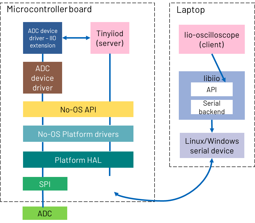
Libiio
It’s written in C, but has bindings in Python, C++, etc. All the high-level apps that talk to libiio are built on top of the stack. The stack preserves its functionality, because of the way things are built, no need to change it, for becoming compatible to use with for ex GNU, Matlab, etc.
ADXL355 Part
The ADXL355 is a Low Noise, Low Drift, Low Power, 3-Axis MEMS Accelerometer.
Features:
Digital SPI and I2C interfaces supported
20-bit ADC
Data interpolation routine for synchronous sampling
Programmable high- and low-pass digital filters
0 g offset vs. temperature (all axes): 0.15 mg/°C maximum
VSUPPLY with internal regulators: 2.25 V to 3.6 V
Hands-on Activity
By the end of this workshop, you will learn:
How to set up a no-OS development environment on Linux
How to build and flash firmware to MAX78000FTHR
How to read sensor data via SPI from ADXL355 accelerometer
How to convert raw register values to meaningful units
How to expose devices through IIO for PC application interaction
Materials
MAX78000FTHR evaluation board
EVAL-ADXL355-PMDZ accelerometer module
Jumper wires (6 connections required)
Raspberry Pi 5 or Linux PC as development workstation
USB cable for MAX78000FTHR connection
Pre-requisites
The workshop environment can be set up using one of two methods. Choose the option that best fits your situation:
Option 1: Pre-built Kuiper Image - Recommended for live workshops and quick setup. Everything is pre-installed and ready to use.
Option 2: Manual Setup - For self-paced learning on your own Linux machine or when you want to understand the full setup process.
Option 1: Pre-built Kuiper Image
Use the pre-configured ADI Kuiper image with all tools and dependencies pre-installed. This is the fastest way to get started.
Download the workshop image from:
https://swdownloads.analog.com/cse/kuiper/kuiperv2.0.0/university-workshops/image_pi5.zip
Unzip the downloaded file to extract the image.
Write the image to an SD card by following the Writing the Image to an SD Card guide.
Insert the SD card into your Raspberry Pi 5 and power it on.
Once the Raspberry Pi 5 boots, the environment is ready. Skip to Environment Configuration to configure the environment variables.
Option 2: Manual Setup
Set up the environment manually on a Raspberry Pi 5 or any Linux PC. This option is useful for self-paced learning or development.
Clone the workshop repository and run the setup script:
git clone https://github.com/romandariana/workshop_baremetal
cd workshop_baremetal
chmod +x setup.sh
./setup.sh
The setup creates the following directory structure:
~/workshop_baremetal/
├── setup.sh
├── ai8x-synthesis/
├── MAX78000SDK/
│   └── Libraries/
└── no-OS/
    └── projects/
        └── workshop/
Environment Configuration
After completing either setup option, configure the environment variables:
export MAXIM_LIBRARIES=~/workshop_baremetal/MAX78000SDK/Libraries
export PLATFORM=maxim
export TARGET=max78000
Note
Add these exports to your ~/.bashrc to make them persistent across
terminal sessions.
Example 1: Hello World UART
This first example demonstrates basic UART communication. The firmware prints “Hello World” messages to the serial console, confirming that the development environment is correctly configured.
Open a terminal and navigate to the workshop project directory:
cd ~/workshop_baremetal/no-OS/projects/workshop
Clean any previous build artifacts and build the first example:
make reset
make EXAMPLE=example_1
Connect the MAX78000FTHR to one of your workstation’s USB ports through an USB cable.
Flash the firmware to the MAX78000FTHR:
make EXAMPLE=example_1 run
Open a new terminal and start the serial monitor:
picocom -b 57600 /dev/ttyACM0
You should see “Hello World” messages printed to the console.
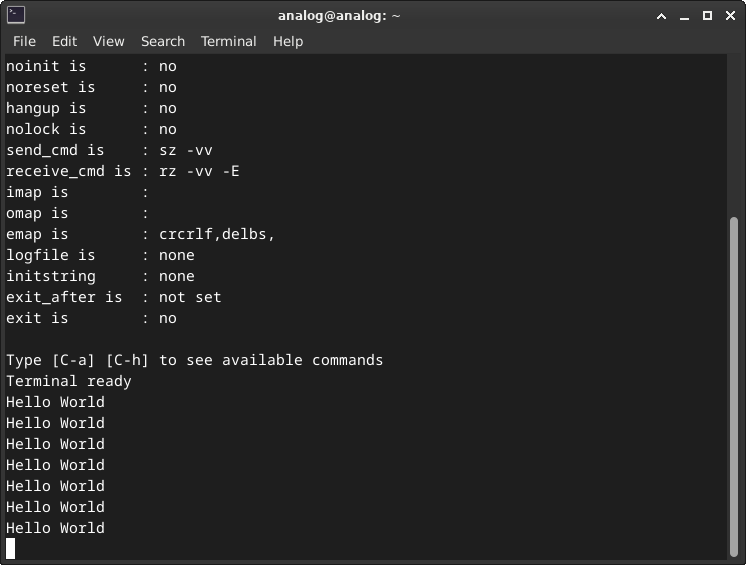
Note
Press Ctrl+A followed by Ctrl+X to exit picocom.
Example 2: Temperature reading
For this example, we connect an accelerometer to the microcontroller board using the provided wires. The scope of this example is to read the temperature from the accelerometer.
Disconnect the MAX78000FTHR from your workstation’s USB port.
Connect the EVAL-ADXL355-PMDZ to MAX78000FTHR using the information below:
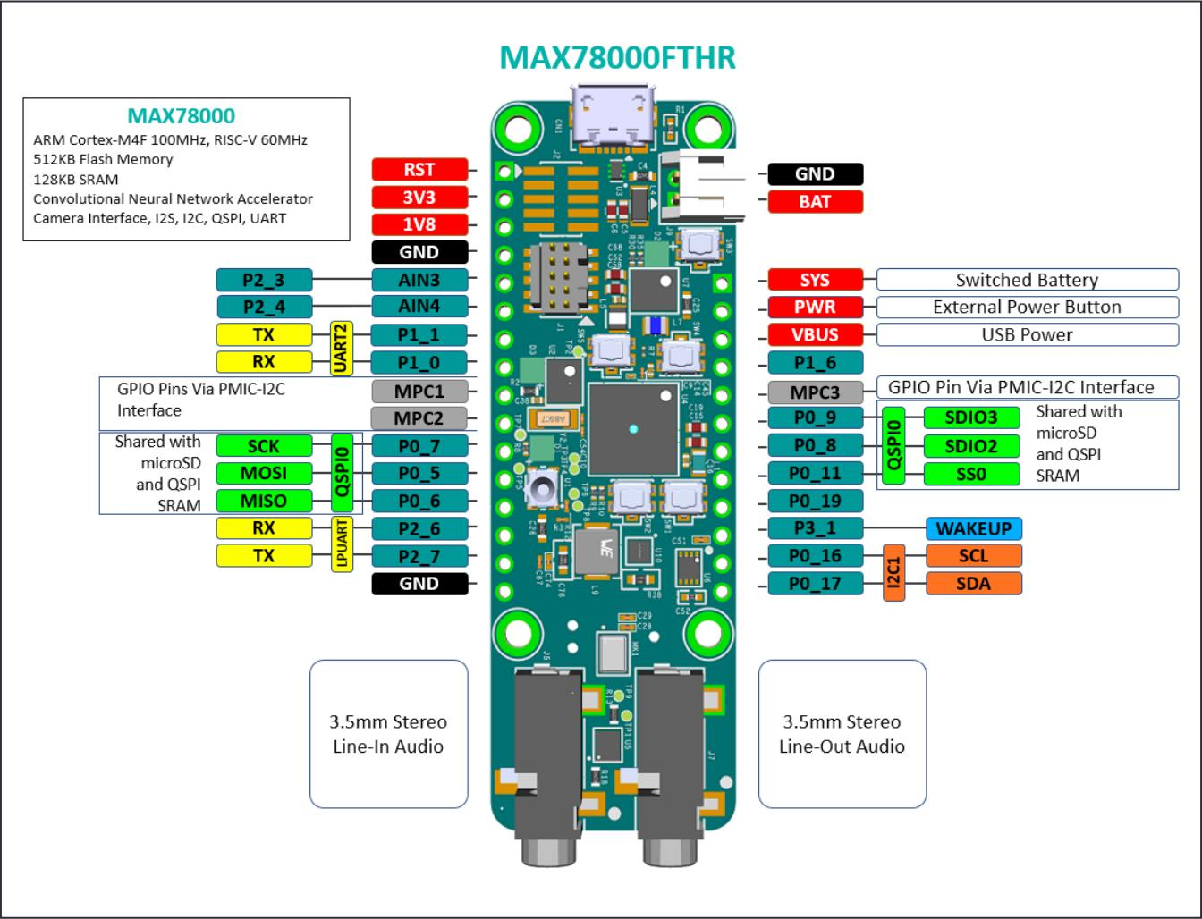
Make sure all 6 wires from the pin correspondence table are connected.
You may now plug in the MAX78000FTHR into one of the workstation’s USB ports using the USB cable.
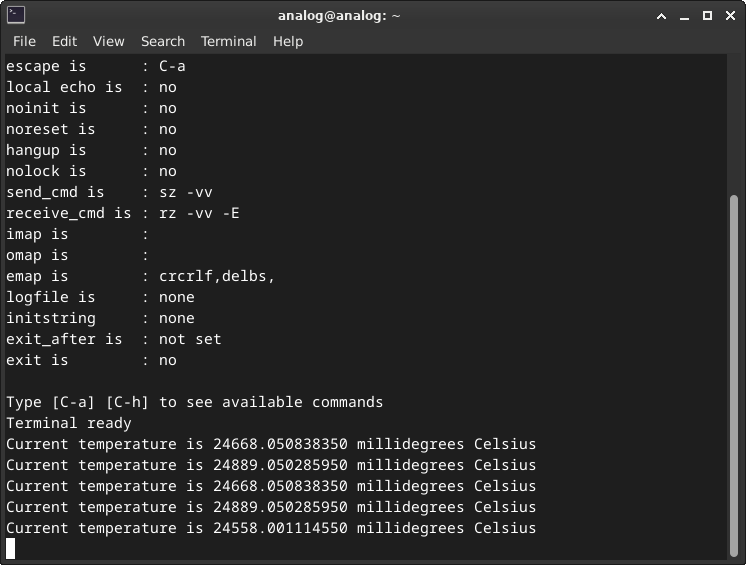
The accelerometer has an internal temperature sensor. This example makes use of this by reading it and displaying temperature values onto the serial terminal.
Clean any previous build artifacts and build the second example:
make reset
make EXAMPLE=example_2
Make sure you have an active terminal running picocom then load the example:
make EXAMPLE=example_2 run
Observe the output being printed every second.
Challenge
Change the current format of the printed temperature from millidegrees to degrees.
Example
The current format is: 24668.050838350 millidegrees.
The new format should be 24.66 degrees.
Hint
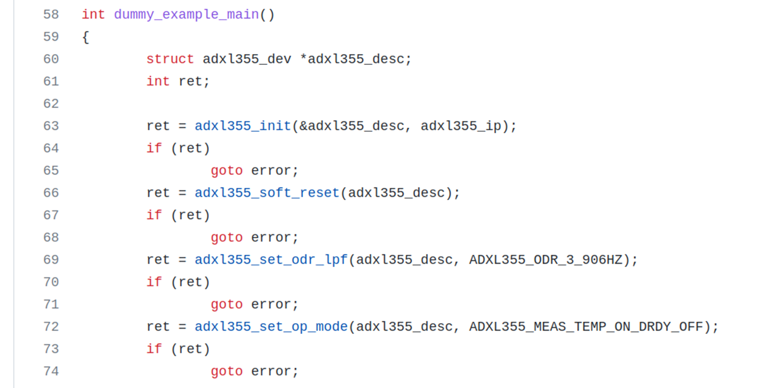
You need to modify example_2.c and then reset, rebuild and reload the program onto the board. The recommended way to do this is to open the no-OS folder using your favorite editor and search for example_2.c file.
code ~/workshop_baremetal/no-OS
Example 3: Raw-to-readable conversion
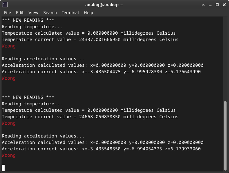
Read temperature and the acceleration values from ADXL355 and convert the data from raw values into user readable values.
Make sure you have an active terminal running picocom, then build and flash the third example:
make reset
make EXAMPLE=example_3
make EXAMPLE=example_3 run
Notice the output displayed:
Challenge
Compute the temperature and the accelerations using the raw values.
Hint
For temperature you need to compute the temp_dividend and temp_divisor.
For accelerometer values you need to compute the x_dividend, y_dividend, z_dividend and accel_divisor.
You need to modify example_3.c and then reset, rebuild and reload the program onto the board. The recommended way to do this is to open the no-OS folder using your favorite editor and search for example_3.c file.
code ~/workshop_baremetal/no-OS
The formula for the temperature:
The formula for the acceleration:
PARAMETER |
VALUE |
|---|---|
TEMPERATURE OFFSET |
-2111.25 |
TEMPERATURE SCALE |
-110.497238 |
ACCELERATION SCALE |
0.00003824593 |
To compute the temperature and the accelerations you can use either the macros
or their values from the above table. The ADXL355_TEMP macros correspond to
the temperature values, and the ADXL355_ACC macros correspond to the
acceleration values.
The raw values from the formulas can be found in the source file under the name
raw_<temp, x, y, z>.
Note
For the division to be correct, the dividend must be represented on twice
the number of bits the divisor is represented on, so you need to cast
explicitly one parameter of the dividend to int64_t.
Example: (int64_t)ADXL355_TEMP_SCALE_FACTOR.
Example 4: IIO Accelerometer Game
This example consists of an accelerometer-enabled game that lets you place components on a circuit by physically tilting the accelerometer.
Close the terminal running picocom.
Make sure you are in the ~/workshop_baremetal/no-OS/projects/workshop
directory and reset the workspace:
make reset
Build the IIO_EXAMPLE of this project:
make EXAMPLE=iio_example
Program the board:
make EXAMPLE=iio_example run
Change the directory and run the game:
cd ~/workshop_baremetal/play
python3 play.py
Notice the graphical interface:
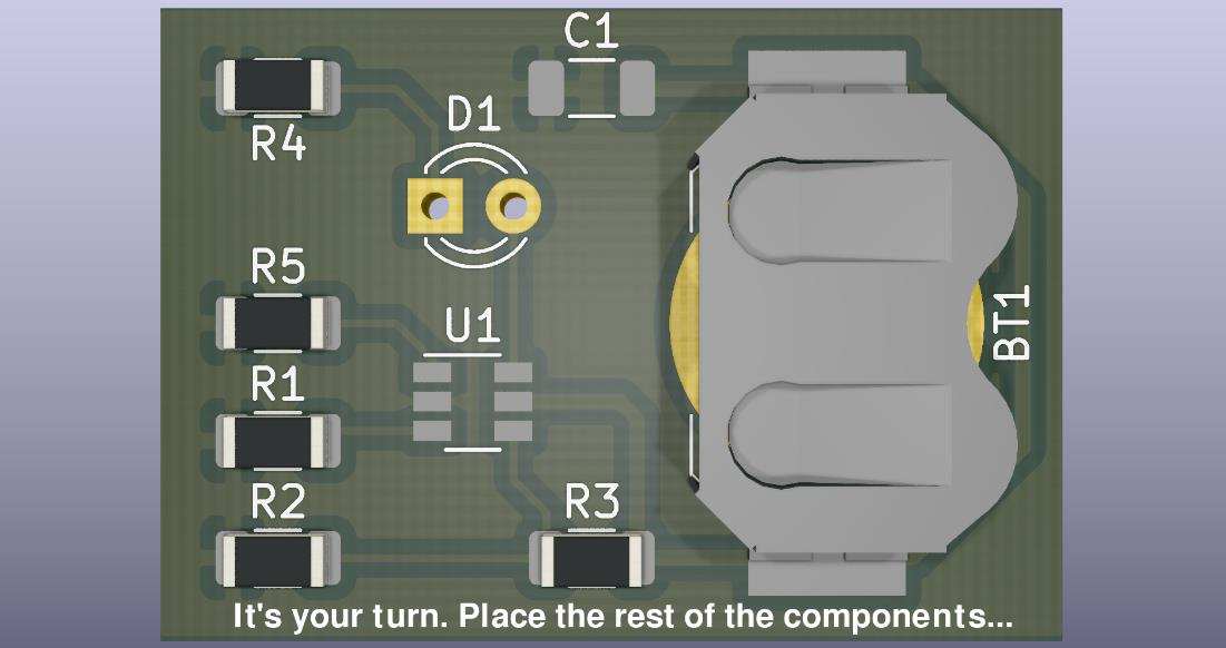
Move the accelerometer board around and observe the output. Be careful not to disconnect the wires.
Let’s see if you can beat the game!
Takeaways
no-OS simplifies embedded development: The framework provides platform-agnostic drivers, eliminating the need to rewrite code for different microcontrollers.
Standardized driver structure: All no-OS drivers follow a consistent pattern with
init(),remove(), and device-specific functions, making it easy to learn and use new drivers.IIO bridges embedded and PC worlds: By exposing devices as IIO endpoints, baremetal firmware can seamlessly integrate with powerful PC applications like IIO Oscilloscope, MATLAB, and Python scripts.
Rapid prototyping: The combination of evaluation boards, reference projects, and build system enables quick bring-up and experimentation.
Open source advantage: With ADI-BSD licensing, no-OS code can be freely used, modified, and integrated into commercial products.
Resources
no-OS
EVAL-ADXL355-PMDZ no-OS projects
en/analog-dialogue/articles/understanding-and-using-the-no-os-and-platform-drivers.html
Hardware
EVAL-ADXL355-PMDZ Product Page
Inspiration