AD936X Advanced
The AD936X Advanced plugin works with Scopy. Changing any field will immediately write changes to the AD936X settings to the hardware, and then read it back to make sure the setting is valid. If you want to set something that the GUI changes to a different number, that means the hardware (either the AD9361 or the FPGA fabric) does not support that mode/precision.
If you want to manipulate the devices behind the back of the GUI (e.g., via
/sys/bus/iio/devices/...), you can still see the settings by clicking the
“refresh” button.
The AD936X Advanced Plugin allows testing of different device driver initialization options and values. In contrast to the controls on the AD936X Main Plugin, the controls here are not part of the main driver API.
In the No-OS driver, the values correspond to members of the setup/init structure.
For the AD9361 Linux Device Driver, each control corresponds to a specific devicetree property.
See more details about AD9361 Customization.
Tip
TIP: After you customize the driver for your application needs, you can read back all values from the Linux debugfs:
root@linaro-ubuntu-desktop:~# cd /sys/kernel/debug/iio/iio\:device1/
root@linaro-ubuntu-desktop:/sys/kernel/debug/iio/iio:device1# grep "" * |
sed "s/:/ = </g" | awk '{print $0">;"}'
adi,2rx-2tx-mode-enable = <1>;
adi,agc-adc-large-overload-exceed-counter = <10>;
[ -- snip -- ]
Simply update the values here: AD9361 Devicetree Initialization
For the No-OS driver, the mapping can be found here: AD9361 Customization
ENSM/Mode/Clocks
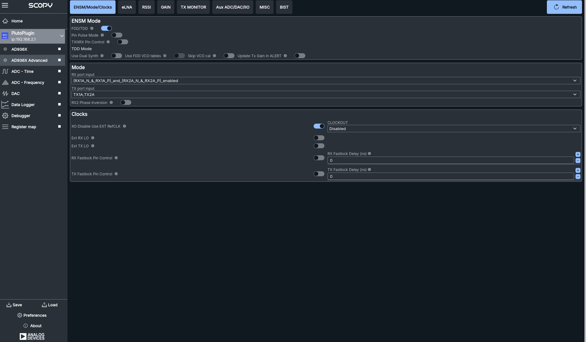
The ENSM/Mode/Clocks section provides configuration for the Enable State Machine (ENSM) mode (FDD/TDD), pin pulse and TXNRX pin controls, and TDD-specific options such as dual synth, VCO tables, and VCO calibration. You can also update Tx gain in ALERT mode.
ENSM Mode: Select between FDD (Frequency Division Duplex) and TDD (Time Division Duplex) operation.
Pin Pulse and TXNRX Pin Controls: Configure the behavior of the ENSM using external pins for mode switching and control.
TDD Options: Enable dual synthesizer operation, configure VCO tables, and perform VCO calibration for TDD applications.
ALERT Mode Gain: Update the transmit gain while in ALERT mode.
RX/TX Port Selection: Choose the RX and TX port inputs and enable RX2 phase inversion.
Clocks: - Disable the crystal oscillator (XO) and use an external reference clock. - Enable external RX/TX local oscillator (LO). - Control RX/TX fastlock pins and set fastlock delays. - Select the output clock mode (e.g., Disabled) for the CLOCKOUT setting. - Configure the Output Clock (
CLK_OUTpin) to output either a buffered version of the external input clock (DCXO) or a divided version of the internal ADC sample clock (ADC_CLK) with selectable division ratios (÷2, ÷3, ÷4, ÷8, ÷16, ÷32, ÷64).
These controls provide flexible and detailed management of the device’s operating modes, clocking, and signal routing, allowing you to optimize the AD936X for a wide range of applications and system requirements.
Gain Control
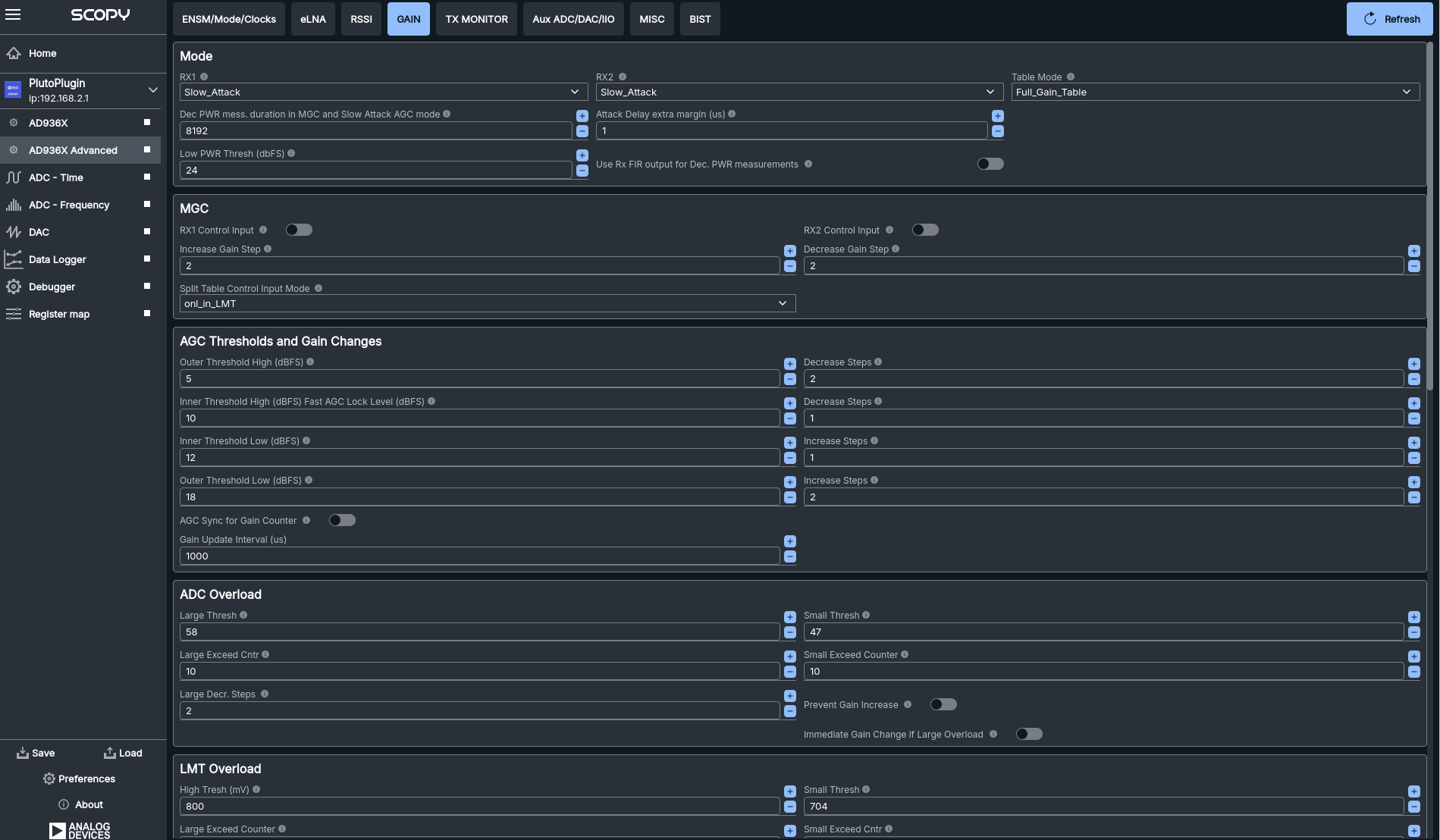
The Gain Control section provides comprehensive configuration for both Manual Gain Control (MGC) and Automatic Gain Control (AGC) modes for RX1 and RX2. Key features include:
Mode: Select gain control mode (e.g., Slow Attack, Fast Attack) for each channel and choose the gain table mode.
Power Measurement and Thresholds: Set power measurement duration, attack delay margin, and thresholds for power detection.
MGC: Configure manual gain steps, control input, and split table input mode.
AGC Thresholds and Gain Changes: Adjust outer/inner thresholds, steps for increasing/decreasing gain, and gain update intervals.
ADC Overload: Set thresholds and counters for large/small ADC overloads, and control gain response to overload events.
LMT Overload: Configure high/low thresholds and counters for LMT overload detection and response.
Digital Gain: Enable digital gain, set maximum digital gain, and configure saturation and decrement step size.
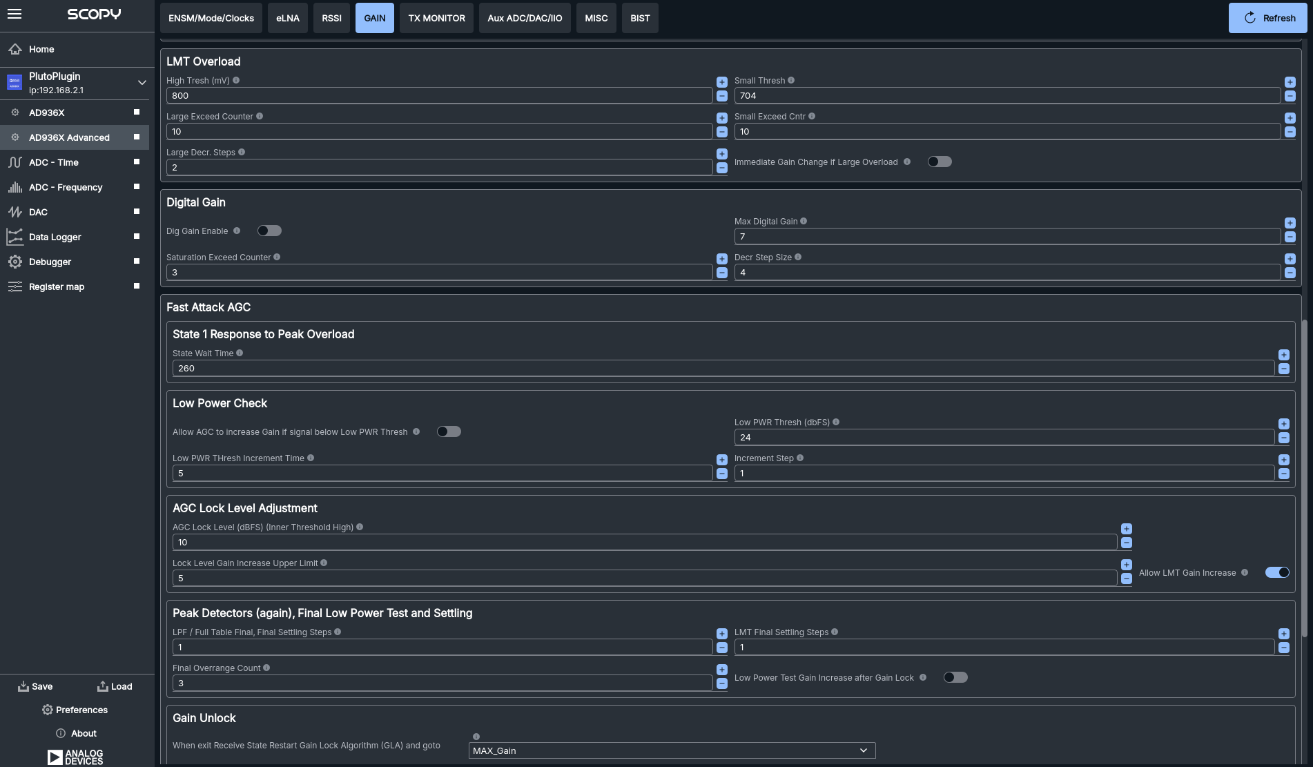
Fast Attack AGC: Fine-tune AGC response to peak overloads and low power conditions.
AGC Lock Level Adjustment: Set lock level and gain increase limits.
Peak Detectors and Final Settling: Configure final settling steps and overrange counts.
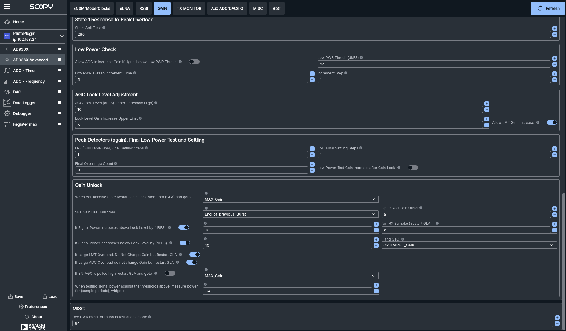
Gain Unlock: Define behavior when exiting gain lock, including gain source, optimized offsets, and response to signal power changes or overloads.
These controls allow for precise and flexible management of the receiver gain, ensuring optimal signal quality and dynamic range in a variety of operating conditions.
RSSI
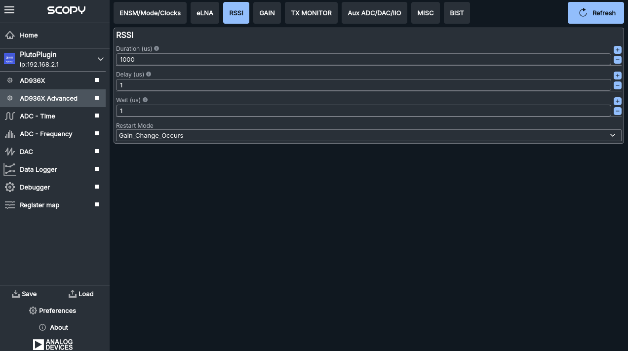
The RSSI (Received Signal Strength Indicator) section allows you to configure: - Duration (µs): The measurement duration in microseconds. - Delay (µs): The delay before the RSSI measurement starts, in microseconds. - Wait (µs): The wait time after the measurement, in microseconds. - Restart Mode: Select the condition for restarting the RSSI measurement (e.g., when a gain change occurs).
These settings provide fine control over how and when RSSI measurements are performed, enabling accurate monitoring and optimization of signal strength in your application.
External LNA
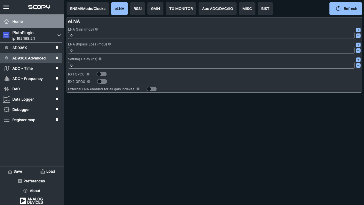
The eLNA (external Low Noise Amplifier) section allows you to configure: - LNA Gain (mdB): Set the gain of the external LNA in milli-decibels. - LNA Bypass Loss (mdB): Specify the loss when the LNA is bypassed. - Settling Delay (ns): Set the settling delay in nanoseconds for the LNA switching. - RX1 GPO0 / RX2 GPO0: Enable or disable GPIO control for RX1 and RX2. - External LNA enabled for all gain indexes: Toggle to enable the external LNA for all gain settings.
These controls allow precise management of the external LNA’s behavior and integration with the receiver chain, optimizing signal quality and noise performance.
TX Monitor
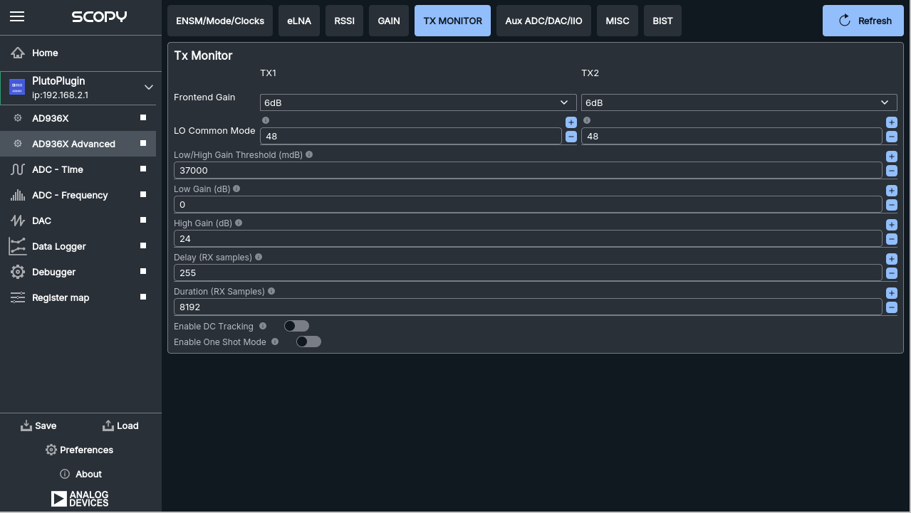
The TX Monitor section provides configuration for monitoring and controlling the transmit (TX) channels (TX1 and TX2). Key features include: - Frontend Gain: Set the gain for each TX channel. - LO Common Mode: Adjust the local oscillator common mode voltage for each channel. - Low/High Gain Threshold (mdB): Set the threshold for switching between low and high gain. - Low Gain / High Gain (dB): Configure the gain values for low and high gain states. - Delay (RX samples): Set the delay in RX samples for monitoring. - Duration (RX samples): Set the duration in RX samples for monitoring. - Enable DC Tracking: Toggle DC tracking for the TX path. - Enable One Shot Mode: Enable or disable one-shot monitoring mode.
These controls allow for detailed monitoring and adjustment of the TX signal path, helping to optimize performance and ensure signal integrity during transmission.
Axillary IO (ADC, DAC, Control IO, Temp Sensor)
The Axillary IO section provides configuration and monitoring for auxiliary analog and digital I/O features of the AD936X, including:
Temp Sensor: - Measurement Interval (ms): Set how often the temperature sensor is sampled. - Offset: Adjust the offset applied to the temperature reading. - Decimation: Set the decimation factor for the temperature sensor data. - Periodic Measurement: Enable or disable periodic temperature measurements.
Aux ADC: - Rate: Set the sampling rate for the auxiliary ADC. - Decimation: Set the decimation factor for the ADC data.
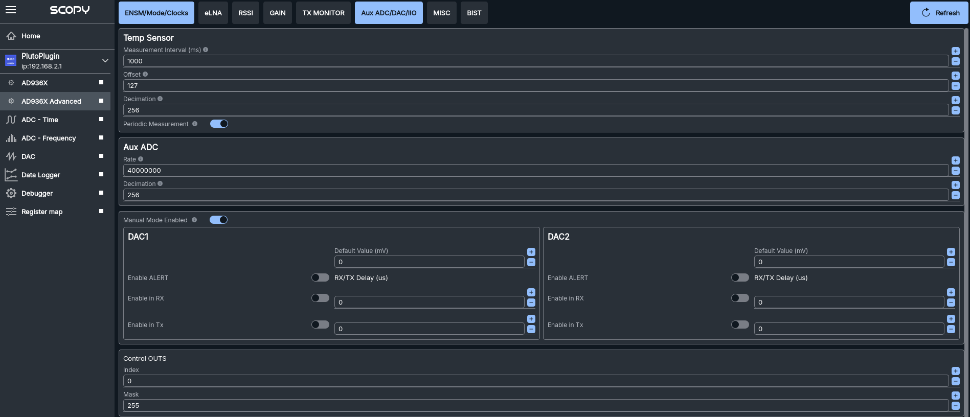
DAC1/DAC2: - Default Value (mV): Set the default output voltage for each DAC channel. - Enable ALERT: Enable alert functionality for the DAC. - Enable in RX/Tx: Enable the DAC output during RX or TX operation, with optional delay settings.
Control OUTS: - Index/Mask: Configure the index and mask for control outputs.
GPO Manual Mode: - Enable: Enable or disable manual mode for General Purpose Outputs (GPOs). - GPO Bit Mask: Select which GPOs are active. - GPO 0-3: For each GPO, configure inactive high state, RX/TX state, and associated delays.
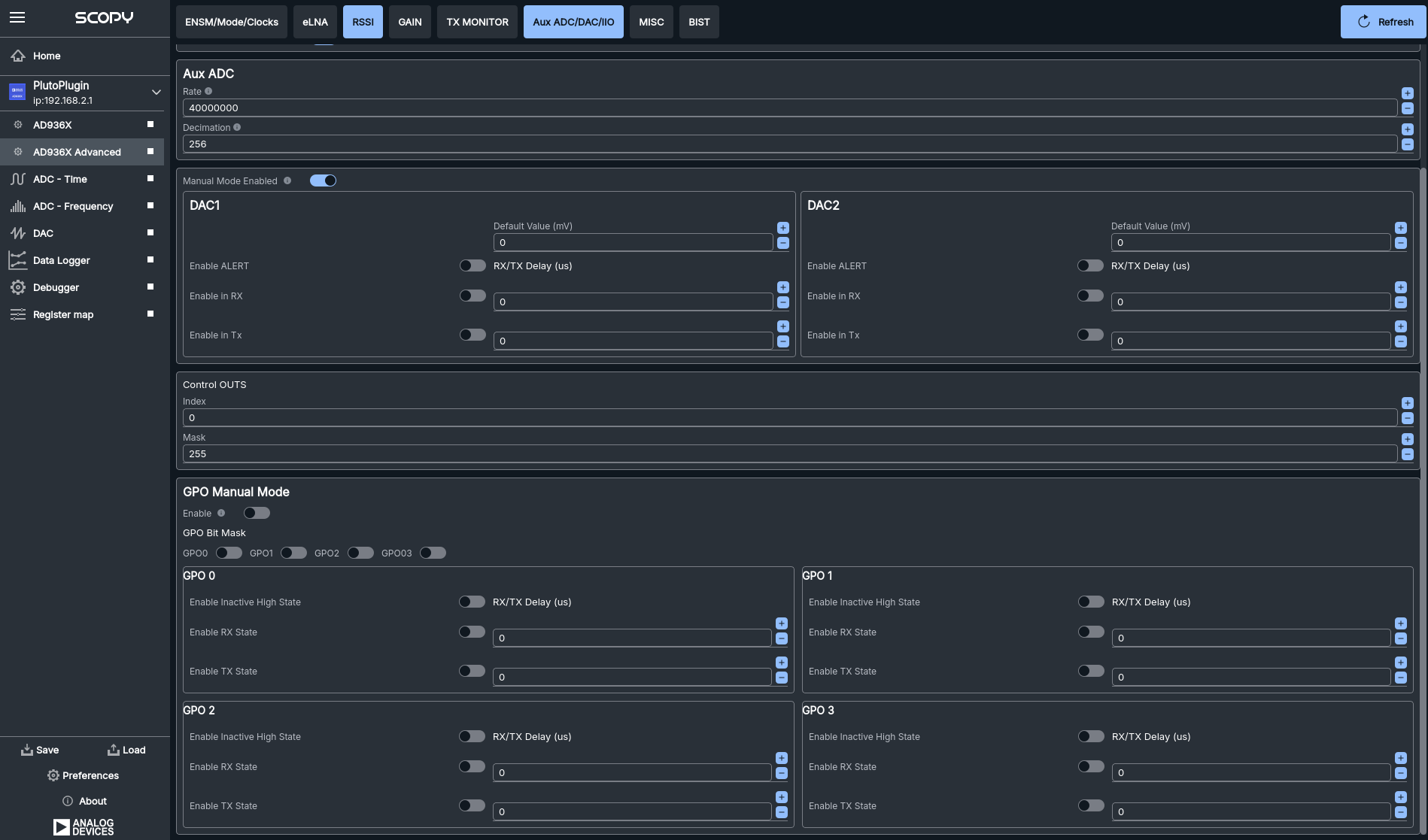
These controls allow for flexible configuration of auxiliary analog and digital I/O, enabling integration with external sensors, actuators, and system monitoring features. The graphical interface provides toggles, sliders, and input fields for each parameter, making it easy to adjust settings and observe their effects in real time.
MISC
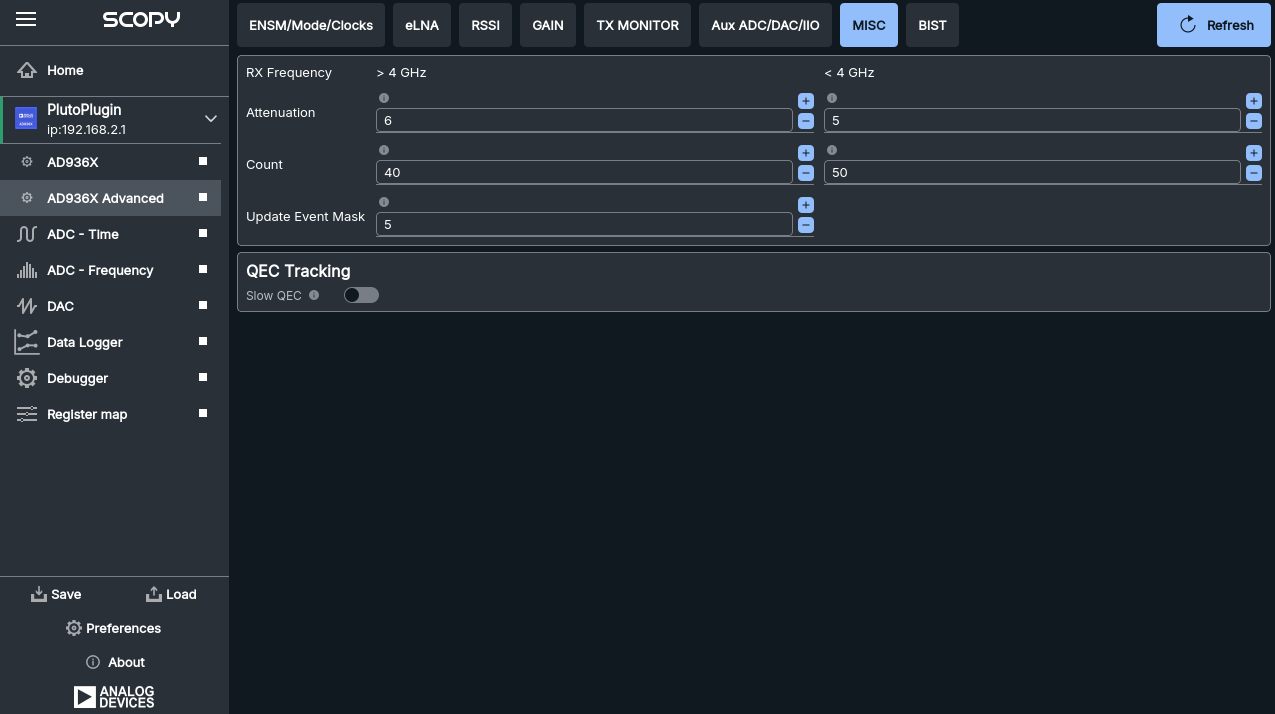
The MISC section provides additional configuration options for the AD936X, including frequency-dependent and tracking features:
RX Frequency: - Separate settings are available for RX frequencies above and below 4 GHz.
Attenuation: - Set the attenuation value for each frequency range.
Count: - Configure the count parameter for each frequency range.
Update Event Mask: - Set the event mask for update events in each frequency range.
These controls allow you to fine-tune the device’s behavior based on the RX frequency, providing flexibility for different operating bands.
QEC Tracking: - Slow QEC: Enable or disable slow Quadrature Error Correction (QEC) tracking. This toggle allows you to optimize QEC performance for your application.
The graphical interface provides input fields and toggles for each parameter, making it easy to adjust and experiment with these advanced settings.
BIST
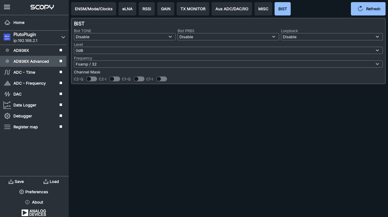
BIST stands for Built-In Self-Test. Selections on this tab take immediate effect and therefore don’t require the Save Settings button. Functionality exposed here is only meant to inject test patterns/data that can be used to validate the Digital Interface or functionality of the device.
There are three major facilities. The topmost drop-down selection box allows you to specify the injection point.
BIST Tone
User selectable tone (with frequency and level selection), that can be injected into the RX or TX path. There are some checkboxes below that allow you to MASK off certain channels. A masked channel (box checked) is not driving any data. (This feature can be useful to determine the I,Q Rx1, Rx2 channel to data mapping.)
BIST PRBS
Pseudorandom Binary Sequence (PRBS) that can be injected into the RX or TX path.
BIST Loopback
Allows either to digitally loopback TX data into the RX path or vice versa.
Digital TX -> Digital RX loopback: The loopback happens inside the AD9361/4 close to the internal digital interface block. The entire RF section is bypassed. This can be used to validate (monitor on RX) the digital samples/symbols sent to the device.
RF RX -> RF TX loopback: The loopback happens in the ADI provided HDL core. The Transmitter will transmit anything that the receiver receives. The entire RF chain is active (Sample rates, RF bandwidth and FIR settings will all affect the transmission.)