JESD Status
Overview
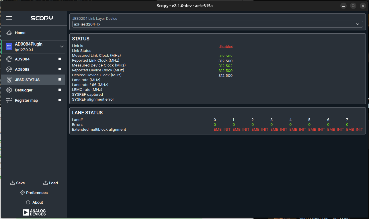
The JESD Status utility plugin provides a graphical interface to monitor the status of JESD204 in Scopy. It allows users to visualize the link and lane status of connected JESD204 devices and provides insights into the lane alignment and other relevant parameters.
Instrument Layout
Comparison with JESD204B Status Utility
Note
The Scopy JESD Status plugin is not a replacement for the existing JESD204B Status utility.
Note
Device compatibility is given by the presence of JESD204B IIO device in the IIO context. Make sure your build exposes the JESD204B IIO device in the device tree (TX and RX).
The Scopy JESD Status plugin does not replace the existing JESD204B Status utility. It is a new tool that provides integration and status monitoring from the same software environment used for device configuration and control.
Check the additional resources section for more information on the JESD204B Status utility.
The main difference between the two tools is in the way of data and status retrieval. The JESD Status plugin uses the IIO context to retrieve the status of the JESD204 link and lanes, while the JESD204B Status utility uses the SYSFS interface to read the status of the JESD204 link and lanes.
The Scopy JESD Status plugin allows users to view the status of JESD204 devices alongside other IIO devices in Scopy.
Detailed Status Information
What |
Description |
|---|---|
Link state (enabled/disabled) |
In case link state is disabled, that either means the link was never enabled or that an error occurred and the FSM rolled back and disabled the link. In the jesd204-fsm case this can be prevented by using the jesd204-ignore-errors; devicetree property when placed in the jesd204-fsm jesd204-top-device node. |
Link status |
Depending on the encoding JESD204B/C 8B10B/64B66B there can be different values RESET, WAIT, CGS, ILAS, etc., DATA Please see link layer documentation for the state machine: JESD204B/C Link Receive Peripheral JESD204B/C Link Transmit Peripheral In general DATA is the desired state indicating proper operation. |
SYNC is asserted/deasserted (8B10B only) |
State of the external SYNC signal |
SYSREF captured (Yes/No) |
Yes indicates that a SYSREF pulse was captured |
SYSREF alignment error (Yes/No) |
Yes indicates that a SYSREF event has been observed which was unaligned, in regards to the LMFC/LEMC period, to a previously recorded SYSREF event. |
Lane rate |
The SERDES lane rate / bit clock |
LMFC/LEMC rate |
Frequency of the internal local multiframe clocks (LMFC)/ local-multiblock-clock (LEMC) |
Lane rate / (40/66) |
Is equal to the desired Link Clock frequency |
Reported Link Clock |
Is the Link Clock frequency which is reported by the common clock framework. If this rate is different from the desired Link Clock frequency, there is likely a problem. For example the clock provider wasn’t able to set the desired value. |
Measured Link Clock |
Is the measured Link Clock, using a frequency counter inside the Link Layer Peripheral. For proper operation desired, reported and measured frequency must match. |
Desired Device Clock |
In case this value is different from the Desired Link Clock, this indicates Dual Clock Operation required by the Gearbox. Please see Gearbox/Dual Clock Operation in the Link Layer Peripheral documentation: JESD204B/C Link Receive Peripheral JESD204B/C Link Transmit Peripheral The Device Clock is typically generated by the clock provider which also provides SYSREF. |
Reported Device Clock |
Is the Device Clock frequency which is reported by the common clock framework. If this rate is different from the desired Device Clock frequency, there is likely a problem. For example the clock provider wasn’t able to set the desired value. |
Measured Device Clock |
Is the measured Device Clock, using a frequency counter inside the Link Layer Peripheral. For proper operation desired, reported and measured frequency must match. |