AD9084
Overview
The AD9084 instrument for Scopy enables integration and control of the Apollo MxFE platform within the Scopy software environment. This plugin allows users to configure and interact with the AD9084 ADC/DAC.
Instrument Layout
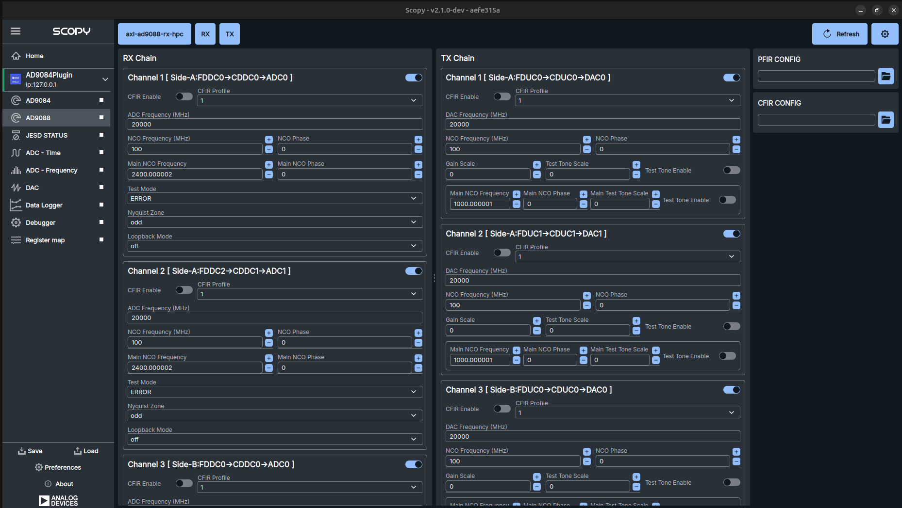
Device name indicator
This is the device that will be used to control the AD9084/AD9088 device. The device name is also used to identify the device in the IIO device tree. Default value is axi-ad9084-rx-hpc.
RX Chain settings
The RX Chain section is a scrollable area containing configuration options for all the RX channels of the device.
All the UI controls are interactive, displaying the state of the current operation, specifically a progress bar while the operation is in progress, becoming green or red based on the success or failure of the operation, respectively. At startup all UI elements are initialized with the current values from the device.
Each RX channel section includes the following information:
Channel indicator: Displays the channel number (e.g., Channel 1, Channel 2, etc.).
Channel label: Indicates the FDDC/CDDC arrangement for the channel.
Channel enable: A checkbox to enable or disable the channel. When successfully disabled, the channel name size will be reduced to indicate that the channel is inactive.
CFIR enable: A checkbox to enable or disable the CFIR filter for the channel.
CFIR profile: A dropdown menu to select the CFIR profile for the channel.
ADC Frequency: Control the ADC frequency. The value is displayed in MHz and it is a shared value for all RX channels. Whenever the value is changed for one channel, a read operation is performed to update all the RX channels with the new value.
NCO Frequency
NCO Phase
Main NCO Frequency
Main NCO Phase
Test Mode
Nyquist Zone: A dropdown menu to select the Nyquist zone for the channel.
Loopback Mode
TX Chain settings
The TX Chain section is a scrollable area containing configuration options for all the TX channels of the device.
All the UI controls are interactive, displaying the state of the current operation, specifically a progress bar while the operation is in progress, becoming green or red based on the success or failure of the operation, respectively. At startup all UI elements are initialized with the current values from the device.
Each TX channel section includes the following information:
Channel indicator: Displays the channel number (e.g., Channel 1, Channel 2, etc.).
Channel label: Indicates the FDUC/CDUC arrangement for the channel.
Channel enable: A checkbox to enable or disable the channel. When successfully disabled, the channel name size will be reduced to indicate that the channel is inactive.
CFIR enable: A checkbox to enable or disable the CFIR filter for the channel.
CFIR profile: A dropdown menu to select the CFIR profile for the channel.
DAC Frequency: Control the DAC frequency. The value is displayed in MHz and it is a shared value for all TX channels. Whenever the value is changed for one channel, a read operation is performed to update all the TX channels with the new value.
NCO Frequency
NCO Phase
Gain Scale
Test Tone Scale
Test Tone Enable
Main NCO Frequency
Main NCO Phase
Main Test Tone Scale
Main Test Tone Enable