FMCOMMS5
Description
The FMCOMMS5 plugin for Scopy provides an interface to control and monitor the AD9361-based FMCOMMS5 hardware. This plugin is designed to work seamlessly with Scopy, allowing users to configure, calibrate, and operate the FMCOMMS5 board for multi-channel RF applications. The plugin supports real-time updates: changing any field will immediately write changes to the hardware and read them back to ensure validity. If a setting is not supported by the hardware or FPGA, the GUI will revert to a valid value.
If you manipulate the device outside of Scopy (e.g., via /sys/bus/iio/devices/...),
you can refresh the plugin view to synchronize settings. For advanced or unsupported
features, refer to the FMCOMMS5 Advanced Plugin.
- The FMCOMMS5 view is divided into several sections:
Device Global Settings
Synchronization Controls
Receive Chain
Transmit Chain
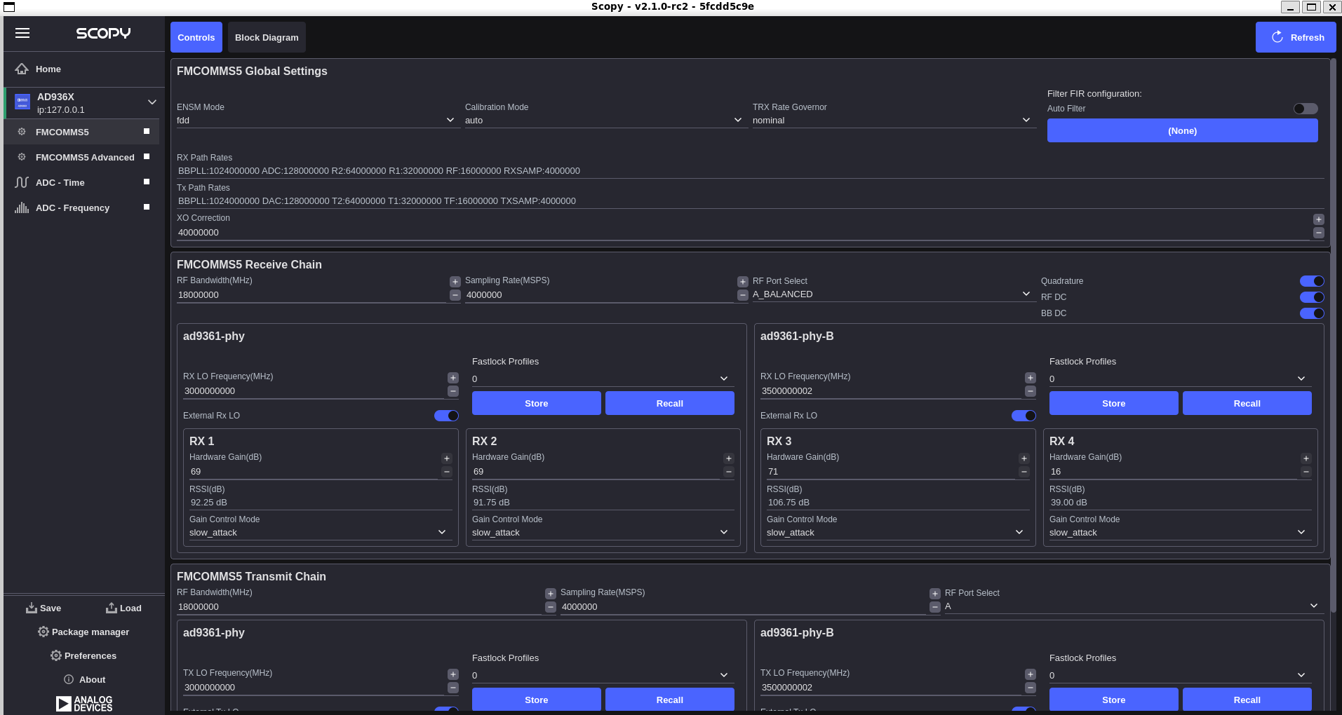
Device Global Settings
Active ENSM: Displays the active mode of the Enable State Machine. (Enable State Machine Controls)
ENSM Modes: Selects one of the available modes: FDD and TDD. (Enable State Machine Controls)
Calibration Mode: Displays the active calibration mode. (Calibration Mode Controls)
TRX Rate Governor: Displays the active option of the Rate Governors. (Rate Governors)
Filter FIR configuration: Allows a FIR filter configuration to be loaded from a file. (Digital FIR Filter Controls)
RX Path Rates: Lists the rates of: BBPLL, ADC, R2, R1, RF, RXSAMP. (List Chosen RX Path Rates)
TX Path Rates: Lists the rates of: TXSAMP, TF, T1, T2, DAC, BBPLL. (List Chosen TX Path Rates)
XO Coarse Tune: Selects the attribute for a coarse tune. (DCXO Tuning)
Synchronization Controls
MCS (Multi-Chip Synchronization): Controls for synchronizing multiple AD9361 chips on the FMCOMMS5 board.
SYNC Status: Displays the synchronization status of all channels.
Trigger Synchronization: Initiate a hardware or software sync event.
Receive Chain
RF Bandwidth(MHz): Configures RX analog filters: RX TIA LPF and RX BB LPF. (RX RF Bandwidth Control)
Sampling Rate(MSPS): Selects the sample rate of the ADC. (Setting/Querying the RX Sample Rate)
RF Port Select: Selects the RF port to be used. Can be either any of the inputs on the Rx input mux (in single ended or differential) or the Tx monitor input. (RF Port Selection)
RX LO Frequency(MHz): Selects the RX local oscillator frequency. Range 70MHz to 6GHz with 1Hz tuning granularity. (Local Oscillator Control)
External RX LO: Allows switching between external and internal LO on the fly. (External LO Support)
Fastlock Profile: Selects one of the 8 available profiles of frequency configuration information. (Fastlock Mode)
Store: Stores the current frequency configuration into the profile pointed by Fastlock Profile.
Recall: Recalls the profile pointed by Fastlock Profile.
Tracking (Calibration Tracking Controls)
Quadrature
RF DC
BB DC
RX
Hardware Gain(dB): Controls the RX gain only in Manual Gain Control Mode (MGC). (MGC Setting the Current Gain)
RSSI(dB): Displays the received strength signal level. (Received Strength Signal Indicator (RSSI))
Gain Control: Displays the active gain mode. (RX Gain Control)
Transmit Chain
RF Bandwidth(MHz): Configures TX analog filters: TX BB LPF and TX Secondary LPF. (TX RF Bandwidth Control)
Sampling Rate(MSPS): Selects the sample rate of the DAC. (Setting/Querying the TX Sample Rate)
RF Port Select: Selects the RF port to be used. (RF Port Selection)
TX LO Frequency(MHz): Selects the TX local oscillator frequency. Range 70MHz to 6GHz with 1Hz tuning granularity. (Local Oscillator Control)
External TX LO: Allows switching between external and internal LO on the fly. (External LO Support)
Fastlock Profile: Selects one of the 8 available profiles of frequency configuration information. (Fastlock Mode)
Store: Stores the current frequency configuration into the profile pointed by Fastlock Profile.
Recall: Recalls the profile pointed by Fastlock Profile.
TX
Attenuation(dB): Individually controls attenuation for TX1 and TX2. The range is from 0 to -89.75 dB in 0.25dB steps. (TX Attenuation Control)
RSSI(dB): TX Received Strength Signal Indicator. Active when TX_MONITOR port is selected in the RX RF Port Select. (TX Received Strength Signal Indicator (TX RSSI))
Block Diagram
The block diagram of the FMCOMMS5 device is available in the “Block Diagram” tab for your reference.