ADRV9009
Description
The ADRV9009 plugin integrates with Scopy to provide comprehensive control and configuration for ADRV9009 transceiver devices. You should always use the latest version if possible. Changing any field will immediately write changes to the ADRV9009 settings to the hardware, and then read it back to make sure the setting is valid. If you want to set something that the GUI changes to a different number, that means the hardware (either the ADRV9009 transceiver or the FPGA fabric) does not support that mode/precision.
If you want to manipulate the devices behind the back of the GUI (e.g., via /sys/bus/iio/devices/...), you can still see the
settings by clicking the “Refresh” button at the top.
If you think the device has a setting that isn’t managed by this tab, check out the ADRV9009 Advanced Plugin for Scopy.
- The ADRV9009 view is divided into five main sections:
ADRV9009 Global Settings
ADRV9009 Receive Chain
ADRV9009 Transmit Chain
ADRV9009 Observation RX
FPGA Settings
Multi-Device Support
The ADRV9009 plugin supports multi-device configurations for applications requiring synchronized operation across multiple transceivers. When multiple ADRV9009 devices are detected, the plugin automatically enables multi-device mode and provides:
Automatic Device Detection: Detection and enumeration of all connected ADRV9009-phy devices
Multi-Chip Sync (MCS): Synchronized operation across multiple devices with automatic or manual synchronization
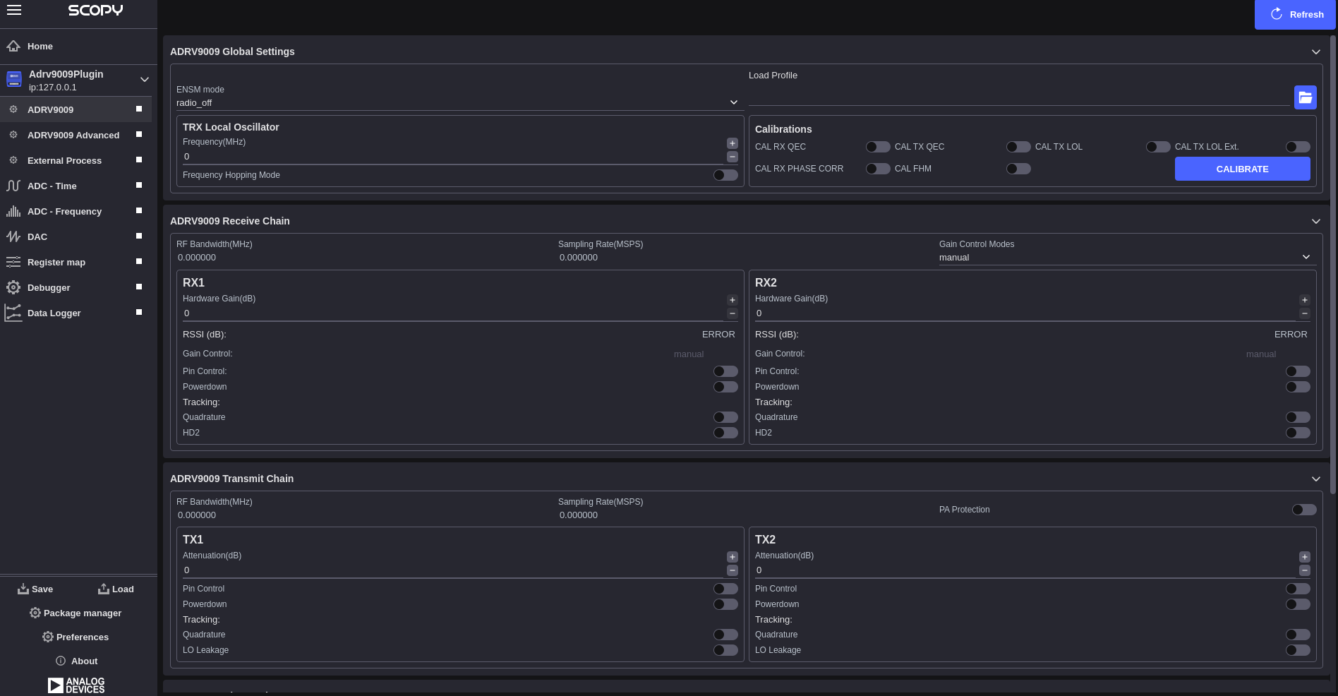
ADRV9009 Global Settings
The global settings section provides device-wide configuration options that affect the overall operation of the ADRV9009 transceiver:
Profile Configuration: Allows loading of device profiles from configuration files
Clock Configuration: Configuration of device clock settings and reference sources
Calibration Control: Access to device calibration functions and status
Receive Chain
The receive chain section controls the ADRV9009 receiver path configuration:
- Section-Level Controls (Shared):
RF Bandwidth(MHz): Display of current analog filter bandwidth
Sampling Rate(MSPS): Display of current ADC sampling rate
Gain Control Modes: Dropdown selection for section-wide gain control mode
- RX Channel Configuration (Per RX1/RX2):
Hardware Gain(dB): Manual gain control range [0-30] dB in 0.5 dB steps
RSSI (dB): Display of received signal strength indication
Gain Control: Display of current gain control mode for this channel
Pin Control: Enable/disable checkbox for gain control pin mode
Powerdown: Enable/disable checkbox to power down the channel
- Tracking Controls (Per Channel):
Quadrature: Enable/disable checkbox for quadrature tracking calibration
HD2: Enable/disable checkbox for second harmonic distortion tracking
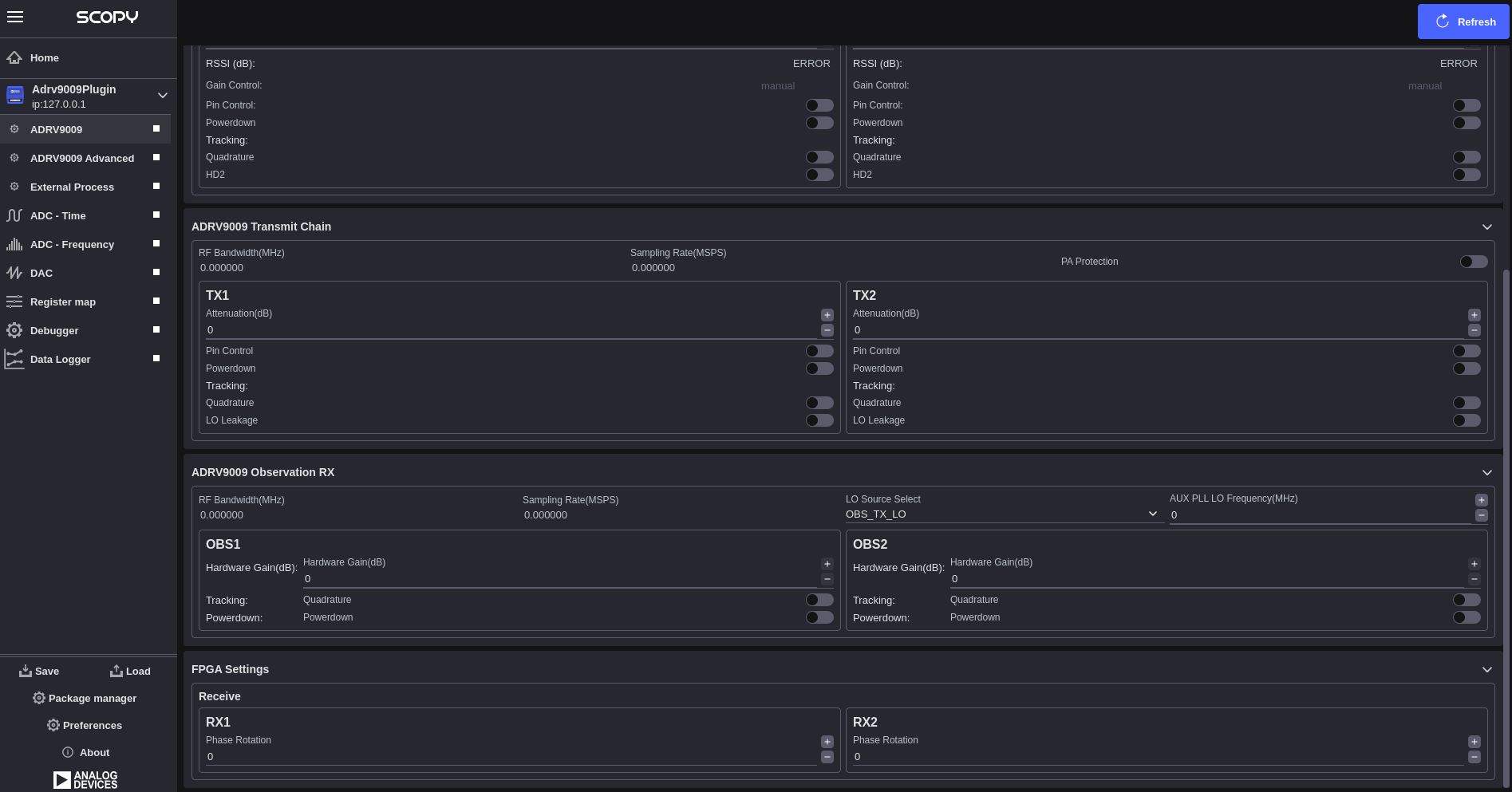
Transmit Chain
The transmit chain section controls the ADRV9009 transmitter path configuration:
- Section-Level Controls (Shared):
RF Bandwidth(MHz): Display of current analog filter bandwidth (determined by profile)
Sampling Rate(MSPS): Display of current DAC sampling rate (determined by profile)
PA Protection: Enable/disable checkbox for power amplifier protection
- TX Channel Configuration (Per TX1/TX2):
Attenuation(dB): Manual attenuation control range [0 to -41.95] dB in 0.05 dB steps
Pin Control: Enable/disable checkbox for attenuation control pin mode
Powerdown: Enable/disable checkbox to power down the channel
- Tracking Controls (Per Channel):
Quadrature: Enable/disable checkbox for quadrature tracking calibration
LO Leakage: Enable/disable checkbox for local oscillator leakage tracking
Observation RX
The Observation RX section provides configuration for the ADRV9009’s observation receiver path:
- Section-Level Controls (Shared):
RF Bandwidth(MHz): Display of current observation filter bandwidth (determined by profile)
Sampling Rate(MSPS): Display of current observation ADC sampling rate (determined by profile)
LO Source Select: Dropdown for RF port selection from available observation sources
Aux PLL LO Frequency(MHz): Auxiliary PLL LO frequency
- ORX Channel Configuration (Per OBS1/OBS2):
Hardware Gain(dB): Manual gain control range [0-30] dB in 1 dB steps
Quadrature: Enable/disable checkbox for quadrature tracking calibration
Powerdown: Enable/disable checkbox to power down the observation channel
FPGA Settings
The FPGA settings section provides control over FPGA-based signal processing functions:
- Phase Rotation (RX Only):
RX1 Phase Rotation: Individual phase adjustment [-180 to +180] degrees
RX2 Phase Rotation: Individual phase adjustment [-180 to +180] degrees
Multi-Chip Synchronization (MCS)
When multiple ADRV9009 devices are present, the MCS Sync functionality ensures synchronized operation.
Configuration and Profiles
- Profile Management:
Load Profile: Import device configuration from file
Profile Validation: Automatic validation of loaded configurations
Profile Application: Apply profiles to hardware with verification
- Refresh and Synchronization:
Refresh Button: Re-read all device settings from hardware
Real-time Updates: Automatic hardware synchronization
Troubleshooting
- Device Detection Issues:
Verify ADRV9009 device is properly connected
Check device drivers and libiio installation
Ensure device enumeration in IIO context
- Synchronization Problems:
Verify HMC7044 clock distributor configuration
Check JESD204 link status
Use manual MCS sync if automatic sync fails
- Calibration Issues:
Allow device warm-up time before calibration
Check RF signal levels and connections
Verify profile compatibility with hardware
- Performance Issues:
Verify sampling rates are within device specifications
Check RF bandwidth settings
Monitor temperature and power supply stability