AD9371
General Description
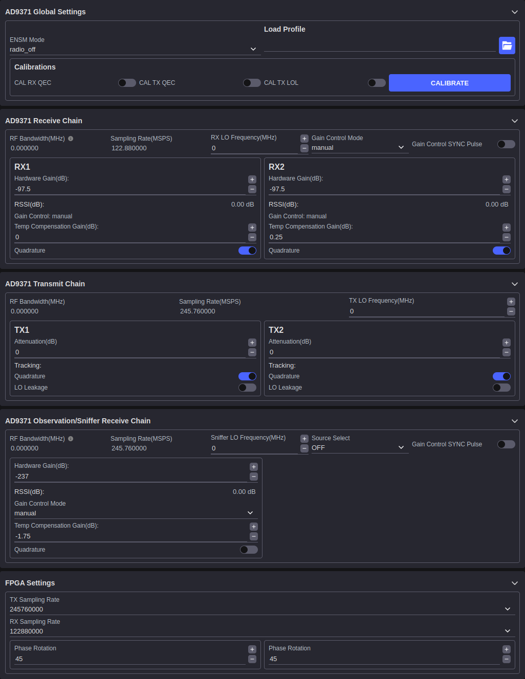
The AD9371 plugin provides real-time hardware configuration for the AD9371 RF transceiver. Changes applied in the UI are written to the device driver immediately and the values are read back to confirm acceptance. This live read-back ensures that the displayed values always reflect the actual hardware state.
Device Global Settings
Active ENSM: Displays the current Enable State Machine mode. The ENSM mode determines the operational state of the device (e.g., Alert, FDD, WAIT).
ENSM Modes: Selects the desired operational mode from the available options.
RX QEC Enable: Enables or disables the Receive Quadrature Error Correction calibration.
TX QEC Enable: Enables or disables the Transmit Quadrature Error Correction calibration.
TX LOL Enable: Enables or disables the Transmit Local Oscillator Leakage calibration.
Profile: Loads a device profile from a file to configure baseband filter and clock settings for a specific sample rate and bandwidth combination.
Receive Chain
RF Bandwidth: Displays the configured receive signal bandwidth in MHz.
Sampling Rate: Displays the RX sample rate in MSPS.
RX LO Frequency: Sets the receive local oscillator frequency. Tunable from 300 MHz to 6 GHz.
Hardware Gain: Sets the receive gain when in Manual Gain Control (MGC) mode. This control is only active when the gain control mode is set to Manual.
RSSI: Displays the Received Signal Strength Indicator in dBFS. This value is read back from the device periodically.
Gain Control Mode: Selects the gain control mode for the receive path.
Manual (MGC): Gain is set directly by the Hardware Gain control.
Hybrid: A combination of automatic and manual gain control.
Automatic (AGC): Gain is managed autonomously by the device.
Quadrature Tracking: Enables continuous quadrature calibration tracking on the receive path.
Transmit Chain
RF Bandwidth: Displays the configured transmit signal bandwidth in MHz.
TX LO Frequency: Sets the transmit local oscillator frequency. Tunable from 300 MHz to 6 GHz.
Attenuation (TX1): Sets the attenuation for transmit channel 1. Adjustable from 0 dB to –41.95 dB in 0.05 dB steps.
Attenuation (TX2): Sets the attenuation for transmit channel 2. Adjustable from 0 dB to –41.95 dB in 0.05 dB steps.
TX QEC Tracking: Enables continuous quadrature error correction tracking on the transmit path.
TX LOL Tracking: Enables continuous local oscillator leakage correction tracking on the transmit path.
Observation / Sniffer Chain
The observation receiver mirrors the structure of the main receive chain and is used to monitor the transmit output for calibration purposes.
RF Bandwidth: Displays the configured observation receiver bandwidth in MHz.
Sampling Rate: Displays the ORx sample rate in MSPS.
ORx LO Frequency: Sets the observation receiver local oscillator frequency.
Hardware Gain: Sets the observation receiver gain in MGC mode.
Gain Control Mode: Selects Manual, Hybrid, or Automatic gain control for the ORx path.
Sniffer LO Frequency: Sets the sniffer port local oscillator frequency for monitoring signals on an auxiliary path.
RF Port Select: Selects which physical RF port the observation receiver is connected to.