AD9375 Advanced
General Description
The AD9375 Advanced plugin extends the AD9371 Advanced tool with three additional configuration tabs exclusive to the AD9375: DPD Setup, CLGC Setup, and VSWR Setup.
All 13 tabs documented in AD9371 Advanced are present in the AD9375 Advanced tool. This page documents only the three additional tabs.
DPD Setup
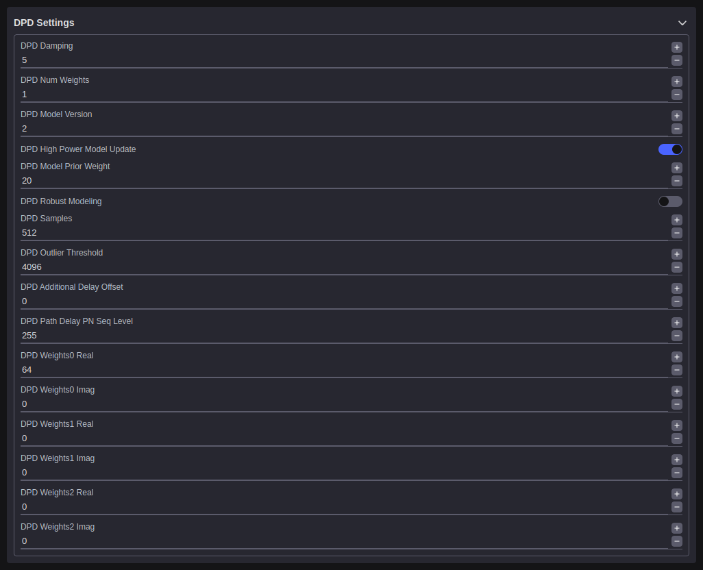
The DPD Setup tab configures the Digital Pre-Distortion model parameters for each transmit channel. DPD linearizes the power amplifier by applying a pre-computed inverse distortion function to the transmit signal.
DPD Actuator Enable (TX1): Enables the DPD actuator on transmit channel 1.
DPD Actuator Enable (TX2): Enables the DPD actuator on transmit channel 2.
DPD Tracking Enable (TX1): Enables continuous DPD model adaptation for TX channel 1.
DPD Tracking Enable (TX2): Enables continuous DPD model adaptation for TX channel 2.
DPD Reset (TX1): Resets the DPD model coefficients for TX channel 1 to their initial values.
DPD Reset (TX2): Resets the DPD model coefficients for TX channel 2 to their initial values.
Model Error (TX1): Displays the current DPD model error metric for TX channel 1. A lower value indicates a better model fit.
Model Error (TX2): Displays the current DPD model error metric for TX channel 2.
Path Delay (TX1): Sets the calibrated signal path delay used by the DPD engine for TX channel 1 (signed 16-bit value, in samples).
Path Delay (TX2): Sets the calibrated signal path delay used by the DPD engine for TX channel 2 (signed 16-bit value, in samples).
Track Count (TX1): Displays the number of DPD adaptation iterations completed for TX channel 1.
Track Count (TX2): Displays the number of DPD adaptation iterations completed for TX channel 2.
DPD Status (TX1): Displays a status code indicating the current state of the DPD engine for TX channel 1.
DPD Status (TX2): Displays a status code indicating the current state of the DPD engine for TX channel 2.
CLGC Setup
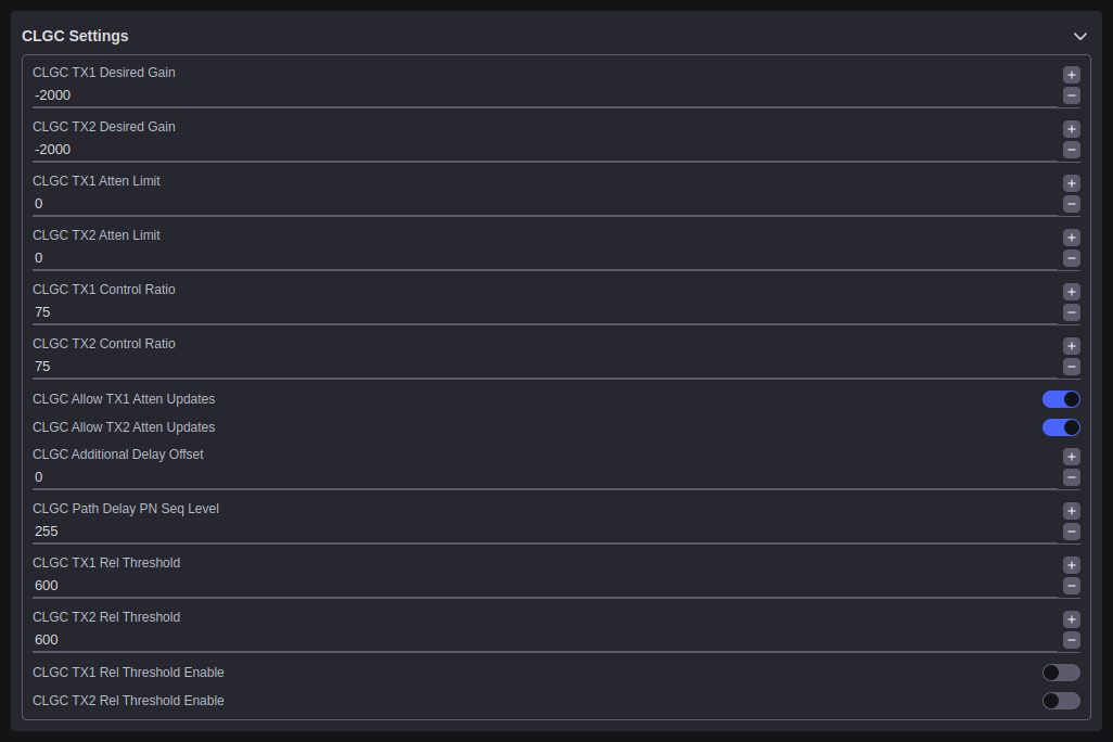
The CLGC Setup tab configures the Closed-Loop Gain Control parameters. CLGC measures the TX output power using the observation receiver and adjusts attenuation to maintain a specified target gain.
CLGC Tracking Enable (TX1): Enables continuous closed-loop gain tracking for TX channel 1.
CLGC Tracking Enable (TX2): Enables continuous closed-loop gain tracking for TX channel 2.
Desired TX1 Gain (mdB): The target gain at the TX1 antenna port in millidecibels. This is a signed 16-bit value.
Desired TX2 Gain (mdB): The target gain at the TX2 antenna port in millidecibels. This is a signed 16-bit value.
Track Count (TX1): Displays the number of closed-loop gain control iterations completed for TX channel 1.
Track Count (TX2): Displays the number of closed-loop gain control iterations completed for TX channel 2.
CLGC Status (TX1): Displays a status code indicating the current state of the CLGC loop for TX channel 1.
CLGC Status (TX2): Displays a status code indicating the current state of the CLGC loop for TX channel 2.
Current TX1 Gain (mdB): Reads back the current measured gain for TX channel 1 in millidecibels.
Current TX2 Gain (mdB): Reads back the current measured gain for TX channel 2 in millidecibels.
TX1 RMS (mdBFS): Displays the RMS power level measured at the TX1 output.
TX2 RMS (mdBFS): Displays the RMS power level measured at the TX2 output.
ORx1 RMS (mdBFS): Displays the RMS power level captured at the observation receiver for TX1 monitoring.
ORx2 RMS (mdBFS): Displays the RMS power level captured at the observation receiver for TX2 monitoring.
VSWR Setup
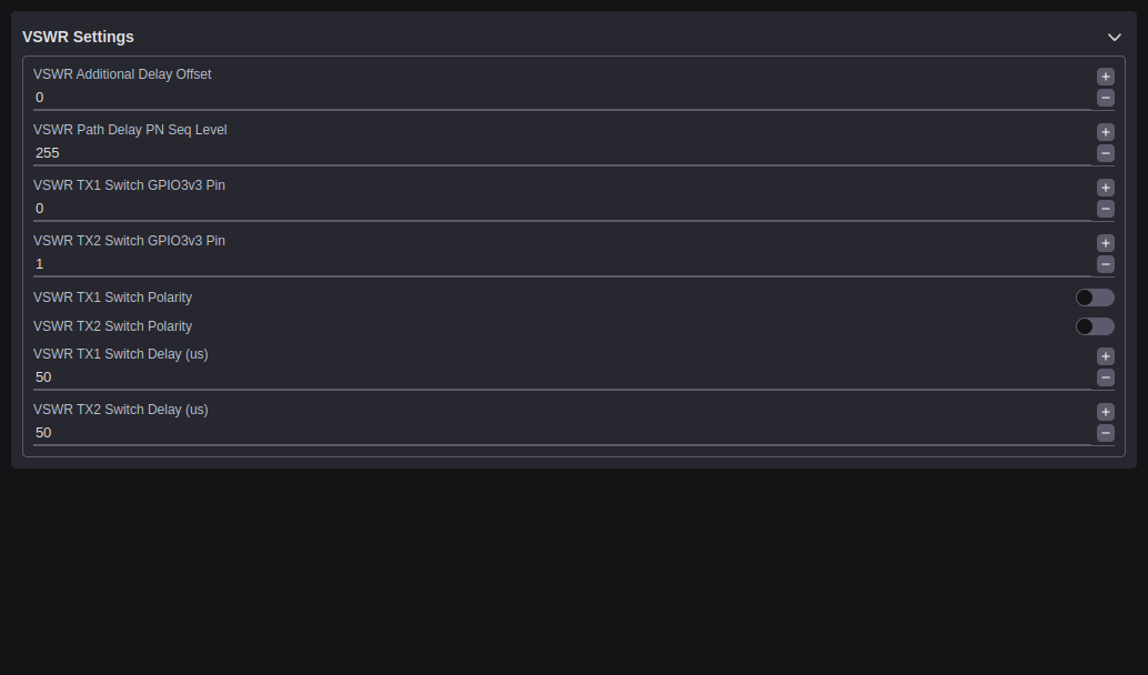
The VSWR Setup tab configures the Voltage Standing Wave Ratio detection engine. VSWR detection compares the forward and reflected signal components at the antenna port using the observation receiver to detect antenna impedance mismatches.
VSWR Tracking Enable (TX1): Enables continuous VSWR monitoring for TX channel 1.
VSWR Tracking Enable (TX2): Enables continuous VSWR monitoring for TX channel 2.
Additional Delay Offset (TX1): Sets an additional signal path delay offset for the VSWR engine on TX channel 1. This is a signed 16-bit value in samples.
Additional Delay Offset (TX2): Sets an additional signal path delay offset for the VSWR engine on TX channel 2. This is a signed 16-bit value in samples.
Track Count (TX1): Displays the number of VSWR measurement iterations completed for TX channel 1.
Track Count (TX2): Displays the number of VSWR measurement iterations completed for TX channel 2.
VSWR Status (TX1): Displays a status code indicating the current state of the VSWR detection engine for TX channel 1.
VSWR Status (TX2): Displays a status code indicating the current state of the VSWR detection engine for TX channel 2.
Forward Gain Real (TX1): The real component of the complex forward path gain for TX1.
Forward Gain Imaginary (TX1): The imaginary component of the complex forward path gain for TX1.
Reflected Gain Real (TX1): The real component of the complex reflected path gain for TX1.
Reflected Gain Imaginary (TX1): The imaginary component of the complex reflected path gain for TX1.
Forward Gain Real (TX2): The real component of the complex forward path gain for TX2.
Forward Gain Imaginary (TX2): The imaginary component of the complex forward path gain for TX2.
Reflected Gain Real (TX2): The real component of the complex reflected path gain for TX2.
Reflected Gain Imaginary (TX2): The imaginary component of the complex reflected path gain for TX2.
ORx Forward (TX1): The forward observation receiver signal level for TX1 monitoring.
ORx Reflected (TX1): The reflected observation receiver signal level for TX1 monitoring.
TX Forward (TX1): The forward transmit signal level measured at the TX1 port.
TX Reflected (TX1): The reflected transmit signal level measured at the TX1 port.
ORx Forward (TX2): The forward observation receiver signal level for TX2 monitoring.
ORx Reflected (TX2): The reflected observation receiver signal level for TX2 monitoring.
TX Forward (TX2): The forward transmit signal level measured at the TX2 port.
TX Reflected (TX2): The reflected transmit signal level measured at the TX2 port.