
CN0540
Description
The CN0540 plugin works with Scopy to control and monitor the CN0540 precision measurement system. The interface is organized as a single scrollable page with four collapsible sections. Checking or unchecking a control writes the new value to hardware immediately and reads it back to confirm the change.
Use the Refresh button in the top bar to re-read all hardware values at any time.
The CN0540 view is divided into four sections:
Power Control
ADC Driver Settings
Sensor Calibration
Voltage Monitor
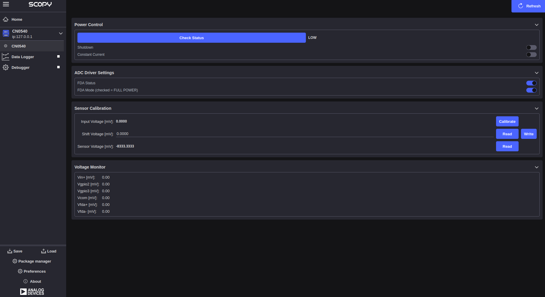
Power Control
The Power Control section manages the GPIO lines that control the device power state and peripheral outputs.
SW_FF: Reads the SW_FF fault flag GPIO and displays the current fault status. Click Check Status to query the hardware.
Shutdown: Enables or disables device shutdown via an active-low GPIO. When the checkbox is checked the device is in normal operation; unchecking activates the shutdown line.
Constant Current: Enables or disables the constant current source output (blue LED GPIO). Checking the box turns the output on.
ADC Driver Settings
The ADC Driver Settings section controls the Fully-Differential Amplifier (FDA) that drives the ADC input.
FDA Status: Enables or disables the FDA amplifier. The underlying GPIO is active-low, so checking this box enables the FDA. The status label reflects the current hardware state.
FDA Mode: Selects the FDA power mode. When checked the FDA operates in FULL POWER mode; when unchecked it operates in LOW POWER mode.
Sensor Calibration
The Sensor Calibration section provides voltage readback and an automated calibration routine that adjusts the DAC shift voltage until the sensor output reads near zero.
Input Voltage [mV]: Displays the ADC input voltage in millivolts, computed from the
ad7768-1voltage0channel asraw × scale. This field is read-only. The Calibrate button on the same row runs an automated calibration loop (up to 20 iterations) that iteratively adjusts the DAC shift voltage until the ADC input reads near zero; the displayed value updates to the final ADC reading when calibration completes.Shift Voltage [mV]: Sets the DAC shift voltage applied to the sensor input. Enter a value in millivolts and click Write to send it to the
ltc2606voltage0channel. Click Read to refresh the displayed value from hardware. The displayed voltage accounts for the output buffer gain factor (DAC_BUF_GAIN = 1.22).Sensor Voltage [mV]: Displays the calculated sensor voltage in millivolts, derived from the ADC reading, DAC shift voltage, FDA gain (2.667), and the FDA output common mode (2500 mV). Click Read to recalculate from current hardware values.
Voltage Monitor
The Voltage Monitor section displays six analog pin voltages read from an
auxiliary ADC (xadc or ltc2308). This section is only visible when a
supported auxiliary ADC device is detected. Voltages are refreshed
automatically every second.
Vin+: Analog input voltage on the positive supply pin.
Vgpio2: Voltage on the GPIO2 pin.
Vgpio3: Voltage on the GPIO3 pin.
Vcom: Common voltage reference level.
Vfda+: FDA positive supply voltage.
Vfda-: FDA negative supply voltage.