FMCOMMS11
Overview
The FMCOMMS11 plugin for Scopy enables control and configuration of the AD-FMCOMMS11-EBZ evaluation board. It provides a unified interface to configure the high-speed RF DAC (AD9162), high-speed ADC (AD9625), input attenuator (HMC1119), and output variable gain amplifier (ADL5240) through the IIO framework.
Supported Devices
AD-FMCOMMS11-EBZ
AD9162 — 16-bit, 12 GSPS RF DAC
AD9625 — 12-bit, 2.5 GSPS ADC
HMC1119 — digital step attenuator (input)
ADL5240 — variable gain amplifier (output)
Getting Started
Prerequisites
AD-FMCOMMS11-EBZ evaluation board with a compatible carrier (e.g., ZC706)
Linux IIO drivers loaded for all four required devices
Scopy version 2.2.0 or later
Using the Plugin
Connect the AD-FMCOMMS11-EBZ to your system and open Scopy. The FMCOMMS11
plugin will be detected automatically when all four IIO devices
(axi-ad9625-hpc, axi-ad9162-hpc, hmc1119, adl5240) are present
on the IIO context. Select the FMCOMMS11 tool from the device tool list to
open the control panel. Changes to any control are written to the hardware
immediately.
Plugin Description
The FMCOMMS11 view is divided into four sections:
ADC
Input Attenuator
DAC
Output VGA
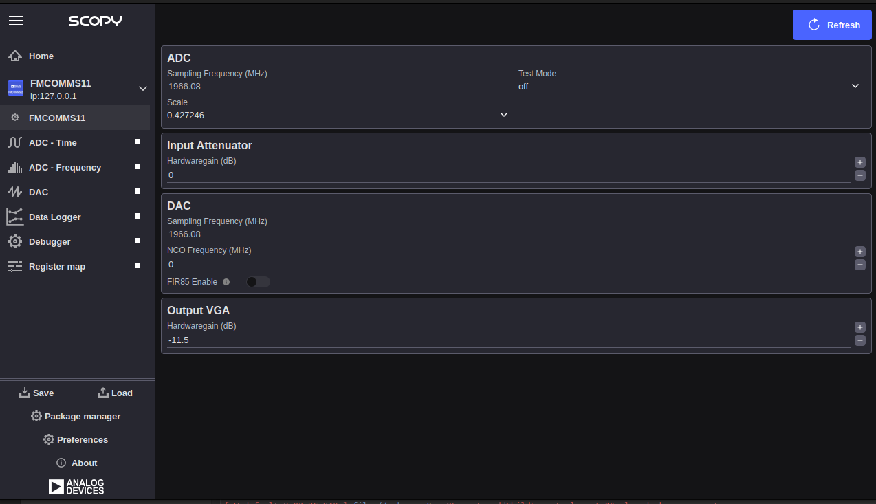
ADC
Sampling Frequency (MHz): Displays the current ADC sampling frequency of the AD9625 in MHz. This field is read-only; the value is read directly from the
sampling_frequencyIIO channel attribute of theaxi-ad9625-hpcdevice and cannot be changed from this panel.Scale: Selects the input voltage scale for ADC channel 0. Available options are populated from the
scale_availableIIO attribute of theaxi-ad9625-hpcdevice.Test Mode: Selects the ADC test pattern mode for channel 0. Available options are populated from the
test_mode_availableIIO attribute of theaxi-ad9625-hpcdevice. Use the normal operating mode during signal acquisition; test modes are used for characterisation and bring-up.
Input Attenuator
Hardware Gain (dB): Sets the attenuation applied by the HMC1119 digital step attenuator on the signal input path. The range is −31.75 dB to 0 dB in steps of 0.25 dB. A value of 0 dB means no attenuation; more negative values increase attenuation. This maps to the
hardwaregainIIO attribute on thehmc1119device.
DAC
Sampling Frequency (MHz): Displays the current DAC sampling frequency of the AD9162 in MHz. This field is read-only; the value is read from the
sampling_frequencyIIO channel attribute of theaxi-ad9162-hpcdevice and cannot be changed from this panel.NCO Frequency (MHz): Sets the numerically controlled oscillator (NCO) frequency for the AD9162 DAC. The range is 0 to 6000 MHz. This maps to the
frequency_ncoIIO attribute on theaxi-ad9162-hpcdevice (channelaltvoltage4if present, otherwisealtvoltage2).FIR85 Enable: Enables or disables the FIR85 digital interpolation filter in the AD9162 DAC signal path. This maps to the
fir85_enableIIO attribute on theaxi-ad9162-hpcdevice (channelvoltage0output).
Output VGA
Hardware Gain (dB): Sets the gain of the ADL5240 variable gain amplifier on the signal output path. The range is −11.5 dB to +20 dB in steps of 0.5 dB. This maps to the
hardwaregainIIO attribute on theadl5240device.
DDS
The direct digital synthesis (DDS) section of the AD9162 DAC — including tone
generation, buffer playback, and TX channel enable — is managed by the generic
DAC plugin in Scopy. That plugin handles the axi-ad9162-hpc DDS tone
frequency, scale, and phase attributes, as well as arbitrary waveform buffer
loading. Refer to the DAC plugin documentation for details.