DAQ2
The DAQ2 plugin works with Scopy. Changing any field will immediately write changes to the DAQ2 settings to the hardware, and then read it back to make sure the setting is valid. If you want to set something that the GUI changes to a different number, that means the hardware (either the AD9680, the AD9144, or the FPGA fabric) does not support that mode or precision.
Features
ADC Monitoring: Displays the ADC sampling frequency read directly from the hardware.
Test Mode Control: Configures each ADC channel independently into one of several built-in test modes (e.g. PN9, PN23, checkerboard) for digital interface validation.
DAC Monitoring: Displays the DAC data clock frequency read directly from the hardware.
Live Refresh: A refresh button re-reads all device attributes from hardware on demand.
Scripting Support: Full JS API (object name
daq2) for automated test control.
Supported Devices
AD-FMCDAQ2-EBZ (AD9680 ADC + AD9144 DAC)
Getting Started
Prerequisites
AD-FMCDAQ2-EBZ evaluation board connected to a supported FPGA carrier
IIO context accessible via network (IP) or USB
Scopy 2.x or later
Using the Plugin
Connect Scopy to the device URI. The DAQ2 plugin is detected automatically when both the
axi-ad9680-hpc and axi-ad9144-hpc IIO devices are present in the context. Once
connected, the ADC and DAC sampling frequencies are read from hardware and displayed. Use the
Test Mode drop-downs to configure the ADC channels, and press the refresh button to re-read all
values from hardware.
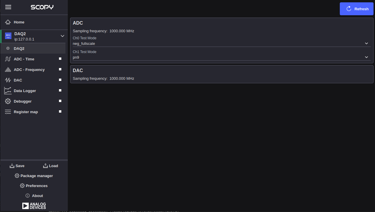
ADC
The ADC section controls the AD9680 analog-to-digital converter
(IIO device axi-ad9680-hpc). Both channels share the same sampling clock
but can be placed into independent test modes.
Sampling Frequency: Displays the ADC sample rate in MHz. This value is read from the hardware once at connect time and is not configurable from this plugin.
Ch0 Test Mode: Selects the built-in test mode for ADC channel 0 (
voltage0). Available options are read from thetest_mode_availableattribute on the hardware. Common values include:off— normal operationmidscale_short— outputs a mid-scale constant valuepos_fullscale— outputs positive full-scaleneg_fullscale— outputs negative full-scalecheckerboard— alternating checkerboard patternpn9— PN9 pseudo-random sequencepn23— PN23 pseudo-random sequenceone_zero_toggle— alternating 0x0000 / 0xFFFF outputramp— incrementing ramp pattern
Ch1 Test Mode: Selects the built-in test mode for ADC channel 1 (
voltage1). Accepts the same options as Ch0 Test Mode.
DAC
The DAC section monitors the AD9144 digital-to-analog converter
(IIO device axi-ad9144-hpc).
Sampling Frequency: Displays the DAC data clock in MHz. This value is read from the hardware once at connect time and is not configurable from this plugin.
Note
DDS tone generation and DAC buffer output controls (One CW Tone, Two CW Tones, Independent I/Q Control, DAC Buffer Output) are part of the full FMCDAQ2 feature set but are not yet available in this Scopy release. For complete device documentation, see the FMCDAQ2 Plugin wiki page.