Applied Systems Control Workshop
This workshop provides an introduction to applied systems control, focusing on practical applications and real-world scenarios. Participants will learn about various control systems, their design and implementation.
Slide Deck and Booklet
Since this tutorial is also designed to be presented as a live, hands-on workshop, a slide deck is provided here:
Download
A complete booklet of the hands-on activity is also provided, either as a companion to following the tutorial yourself:
Download
Theoretical content
Overview of industrial control and automation systems
Introduction to PWM control
Introduction to PID control
AD-SWIOT1L-SL Board Overview
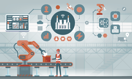
Overview of industrial control and automation systems
Control systems such as computers, PLCs, and robots are utilized to manage industrial processes.
They enhance efficiency, quality, and safety, while lowering operational costs.
Common applications include automated assembly lines and process control in refineries.
An industrial control system is a group of mechanical and/or electronic devices that manage other equipment or systems to control specific devices or various process parameters, such as temperature, humidity, or flow.
Did you know?
The first programmable logic controller (PLC) was invented in 1968 to automate automotive assembly lines, revolutionizing industrial automation.
Examples of systems:
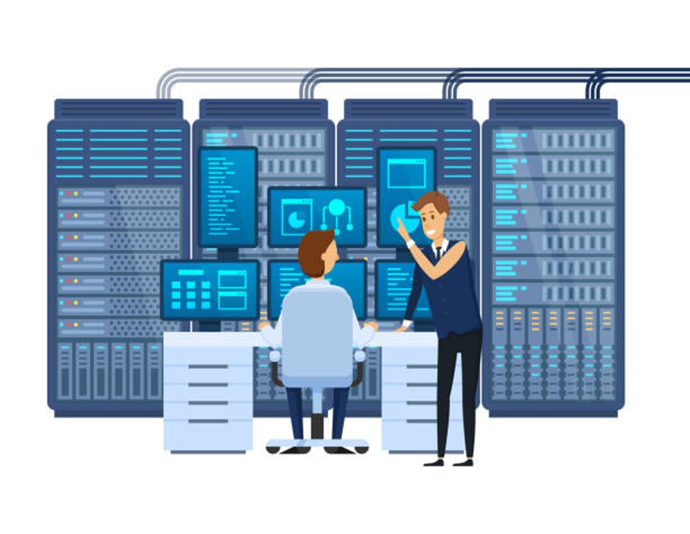
SCADA (Supervisory Control and Data Acquisition): Designed for monitoring and controlling field devices (either locally or remotely). SCADA systems collect, process, and visualize real-time data, and interact with sensors through SCADA software. Data is typically displayed on an HMI (Human-Machine Interface).
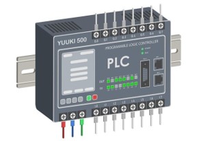
PLC (Programmable Logic Controllers): Modular devices of various sizes that include a microprocessor and a certain number of I/O channels, ranging from dozens to hundreds. PLCs are a fundamental component of industrial systems.
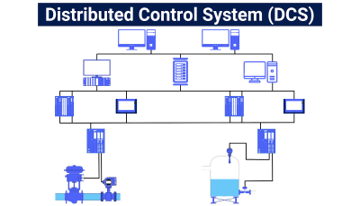
DCS (Distributed Control Systems): Similar in purpose to PLCs, DCSs control and monitor industrial equipment. The main difference is that DCSs use multiple controllers to distribute tasks across the entire system, while PLCs typically have a single centralized controller, making PLCs suitable for simpler control structures and well-defined tasks.
PID: Will be discussed in more detail later.
PAC (Programmable Automation Controller): Combines the features of a PLC and a PC to provide more flexible and high-performance control.
Industrial automation components
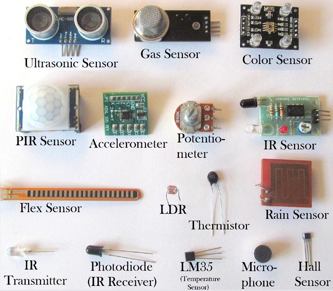
Sensors: Devices that detect changes in the environment and convert them into signals that can be read by a controller. Examples include temperature sensors, pressure sensors, and flow meters.
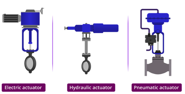
Actuators: Devices that convert control signals into physical actions, such as motors, valves, and pumps.
Controllers: Devices that process input signals from sensors and send output signals to actuators to control the system. Examples include PLCs, DCSs, and PACs.
Human-Machine Interface (HMI): A user interface that allows operators to interact with the control system, monitor its status, and make adjustments as needed.
Communication protocols: Systems that enable data exchange between different components of the control system, such as Ethernet, Modbus, and Profibus.
Power supply: Provides the necessary electrical power to the control system components.
Software: Programs that run on controllers and HMIs to implement control algorithms, monitor system performance, and provide user interfaces.
Common control strategies
PID (Proportional-Integral-Derivative): A widely used control strategy that adjusts the output based on the error between the desired setpoint and the measured process variable. PID controllers are effective for maintaining stable control in various industrial applications.
Feed-forward control: A proactive control strategy that anticipates changes in the process and adjusts the output accordingly, rather than reacting to errors after they occur.
Cascade control: A control strategy that uses multiple controllers in a hierarchical structure to manage complex processes. Each controller operates on a different level, allowing for more precise control and improved system performance.

ON/OFF control: A simple control strategy that switches the output between two states (on and off) based on the process variable. This method is often used in applications where precise control is not required, such as in heating systems.
Introduction to PWM control
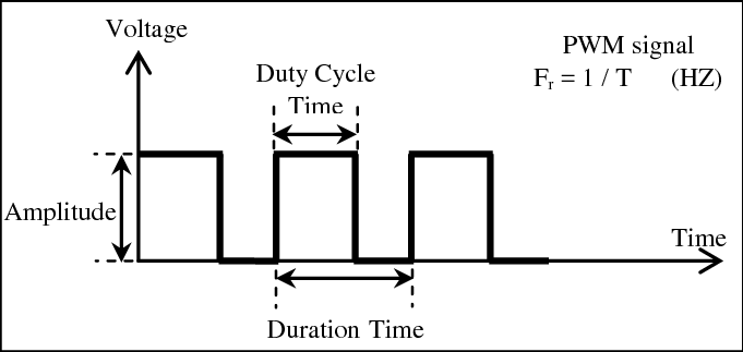
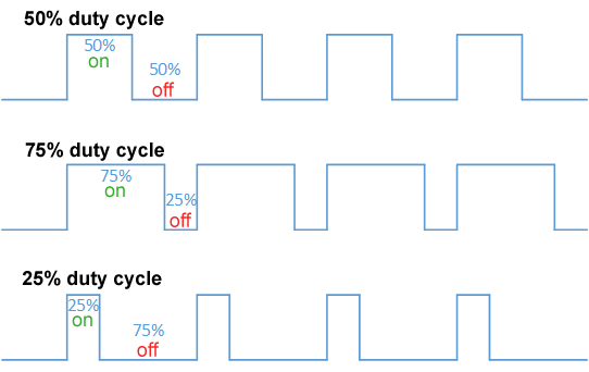
Pulse Width Modulation (PWM) is a technique used to control the power delivered to electrical devices by varying the width of the pulses in a signal. It is commonly used in applications such as motor control, LED dimming, and heating systems. PWM works by switching a signal on and off at a high frequency, with the ratio of the on time to the total cycle time (duty cycle) determining the average power delivered to the load. By adjusting the duty cycle, the effective voltage and current can be controlled, allowing for precise control of devices.
Applications of PWM control include:
Motor speed control: By varying the duty cycle, the speed of DC motors can be adjusted, allowing for smooth acceleration and deceleration.
LED dimming: PWM can be used to control the brightness of LEDs by adjusting the duty cycle, providing energy-efficient lighting solutions.
Heating systems: PWM can be used to control the power delivered to heating elements, allowing for precise temperature control in applications such as ovens and industrial furnaces.
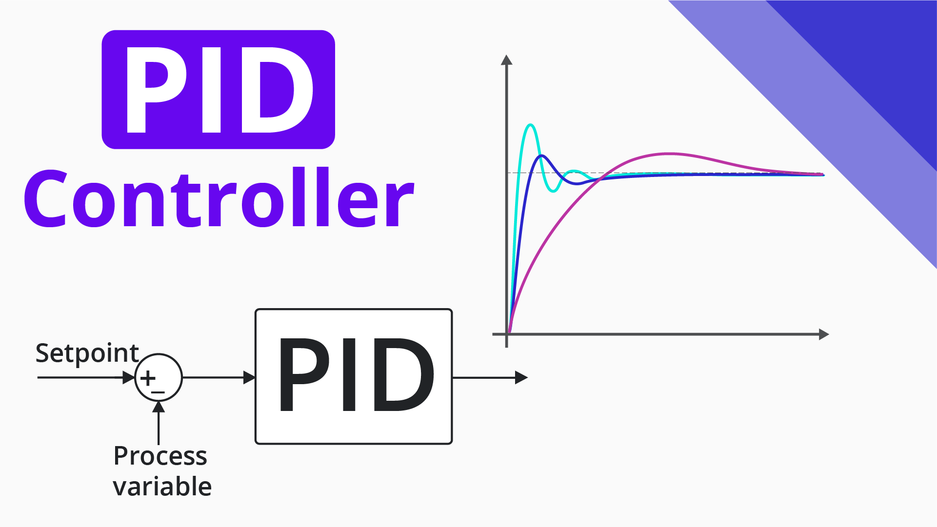
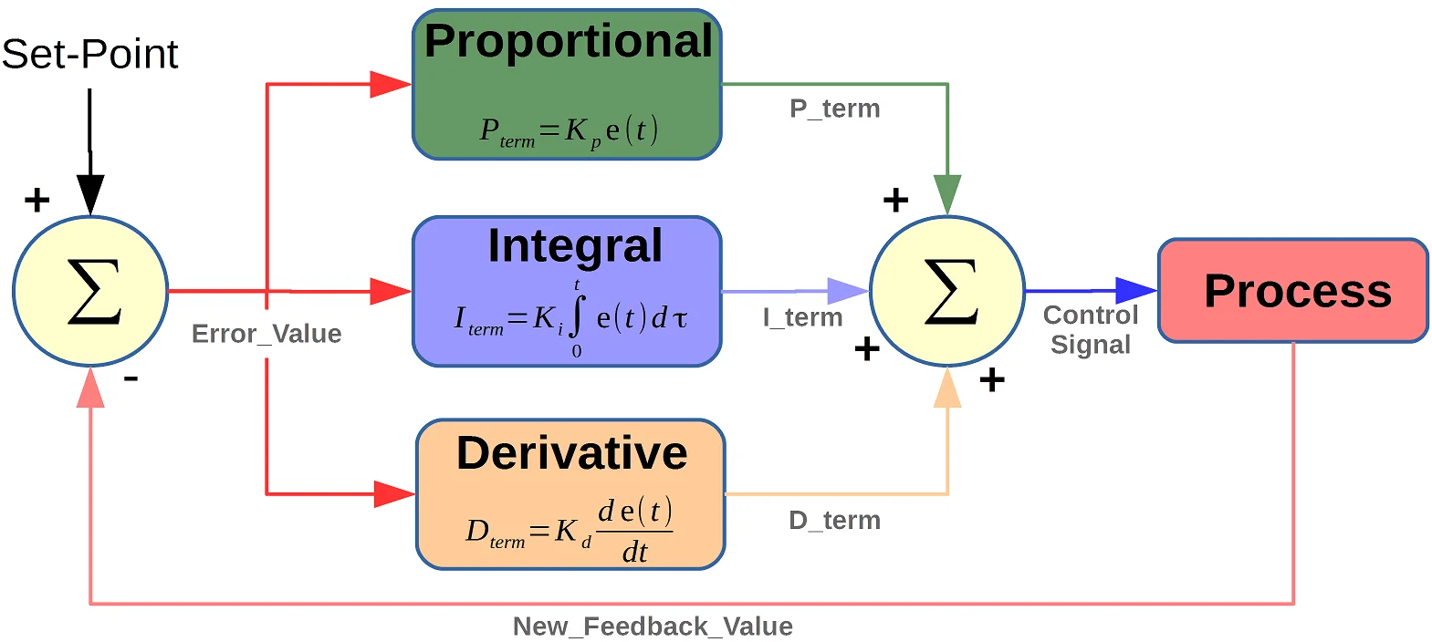
Introduction to PID control
PID (Proportional-Integral-Derivative) control is a widely used control strategy in industrial automation systems. It combines three control actions to maintain a desired setpoint by adjusting the output based on the error between the setpoint and the measured process variable. PID control works by continuously calculating the error and applying a correction based on three terms:
Note
Did you know? The PID control algorithm was first developed in the early 20th century for automatic steering of ships—long before it became a staple in industrial automation.
Proportional (P): The proportional term produces an output that is proportional to the current error. It provides a quick response to changes in the process variable, but may lead to steady-state errors if used alone.
Integral (I): The integral term accumulates the error over time and produces an output that is proportional to the total accumulated error. It helps eliminate steady-state errors by adjusting the output based on the history of the error.
Derivative (D): The derivative term predicts future errors based on the rate of change of the error. It provides a damping effect, reducing overshoot and improving system stability.
PID control is widely used in various applications, including:
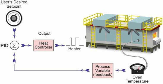
Temperature control: Maintaining a specific temperature in processes such as chemical reactions, heating systems, and HVAC systems.
Speed control: Regulating the speed of motors in applications such as conveyor systems, fans, and pumps.
Position control: Controlling the position of mechanical systems, such as robotic arms and CNC machines
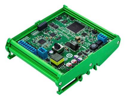
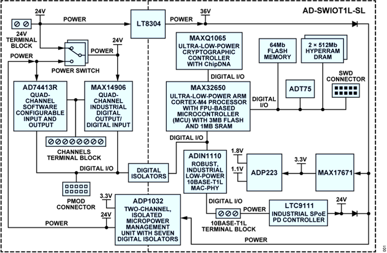
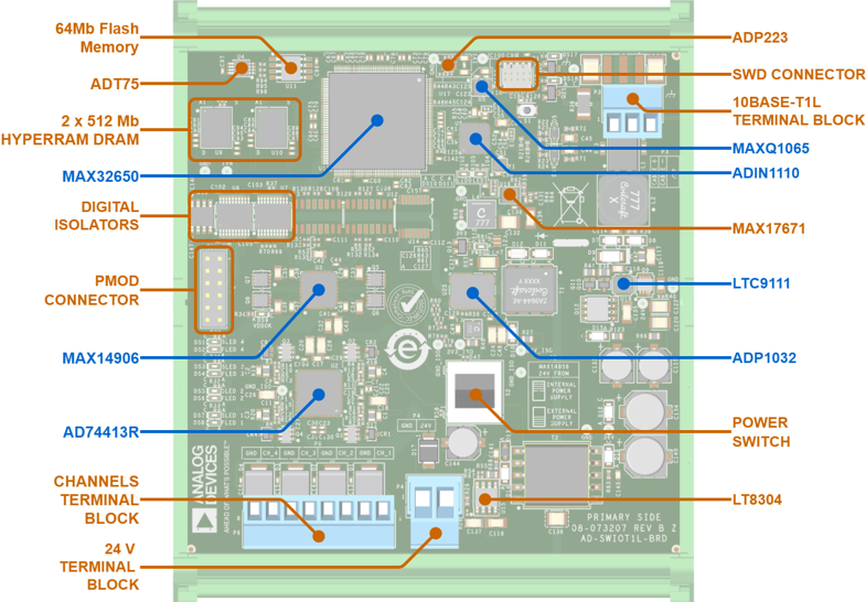
AD-SWIOT1L-SL Board Overview
The AD-SWIOT1L-SL board is a versatile platform designed for industrial control applications. It features a range of components that facilitate the implementation of control strategies, including PWM and PID control.
It includes:
4 x software configurable IO channels
Processing at the edge
Built-in security
10BASE-T1L interface
10-Link expansion PMOD connector
Field and SPE power
Fully isolated design
Industry standard form factor for DIN rail installation
Open-source hardware design and software stack
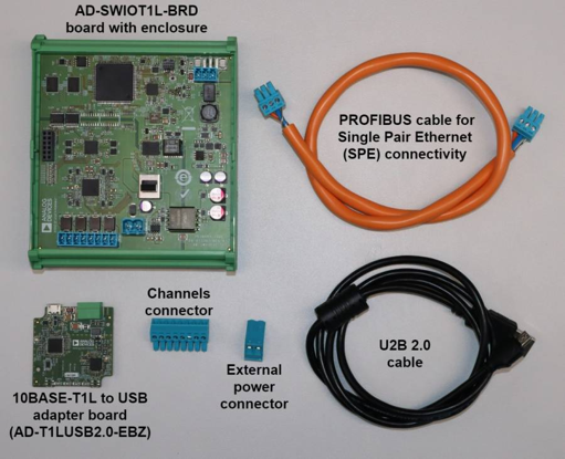
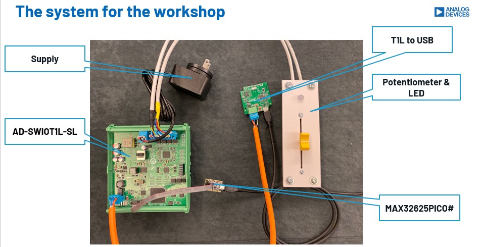
Kit contents
Hands-on activity
Participants will engage in hands-on activities to apply the theoretical concepts learned. The activities will include:
Power on the Raspberry Pi 5 board using a Type-C power supply and boot it.
Power the AD-SWIOT1L-SL board by plugging in the power supply.
Connect the USB to T1L media converter to your Raspberry 5 board using a micro-USB cable.
Connect the USB to T1L media converter to the AD-SWIOT1L-SL board using the PROFIBUS cable. After a short time, both link status LEDs(on the media converter and the board) should be on.
Connect the Raspberry Pi 5 to a display using a HDMI to Micro-HDMI cable, and connect a keyboard and mouse to the USB ports.
In the end, your setup should look like this:
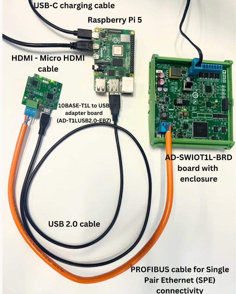
System setup with Raspberry Pi 5 and AD-SWIOT1L-SL boards connected
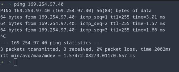
Testing the board connectivity
Open a terminal and run the command:
ping 192.168.97.40This command will rule out the host (RPi 5) network configuration issues.If the ping command is not successful run
sudo ip route add
192.168.97.40 dev eth0
to add a route to the board’s IP address.
Clone the workshop repository:
git clone https://github.com/constmonica/pyadi-iioNavigate to the cloned repository:
cd pyadi-iioCheckout the workshop branch:
git checkout swiotGo to the examples directory:
cd examples/workshop
Exercise 1: Power the RGB LED red, green and blue
Open file exercise_2.py
Use the connector with the RGB LED and plug it into the board.
Write a for loop to power the LED red, green, and blue in sequence.
Run your code and observe the colors change
python3 exercise_2.py
Exercise 2: Adjust the brightness of an LED using a potentiometer
Use the connector with a potentiometer and LED and plug it into the board.
Open file exercise_3.py
Assign the value of the potentiometer to the ADC channel
Run your code.The LED brightness change as you adjust the potentiometer.
python3 exercise_3.py
Exercise 3: PID control loop of temperature using a PWM-controlled fan
Use the connector with a fan and plug it into the board.
Run the pid_control.py script and see how the PWM signal and speed adjust based on temperature.
python3 pid_control.pyMake the
pwm_outputvariable an input from the user and see how the duty cycle affects fan speed.
Workshop Takeaways
Gained practical experience with industrial control systems and their components.
Learned the fundamentals of PWM and PID control strategies and their real-world applications.
Explored the AD-SWIOT1L-SL board and its capabilities for industrial automation.
Developed hands-on skills in configuring hardware and running control algorithms.
Understood the importance of sensors, actuators, controllers, and communication protocols in automation.
Enhanced understanding of how modern industrial systems are designed, monitored, and controlled.
Practiced troubleshooting connectivity and implementing control logic in Python.