AD-ETHERNETAPLDEVICE-SL
Ethernet-APL Field Platform for Intelligent, Safe, Secure, and Connected Industrial Devices
Introduction
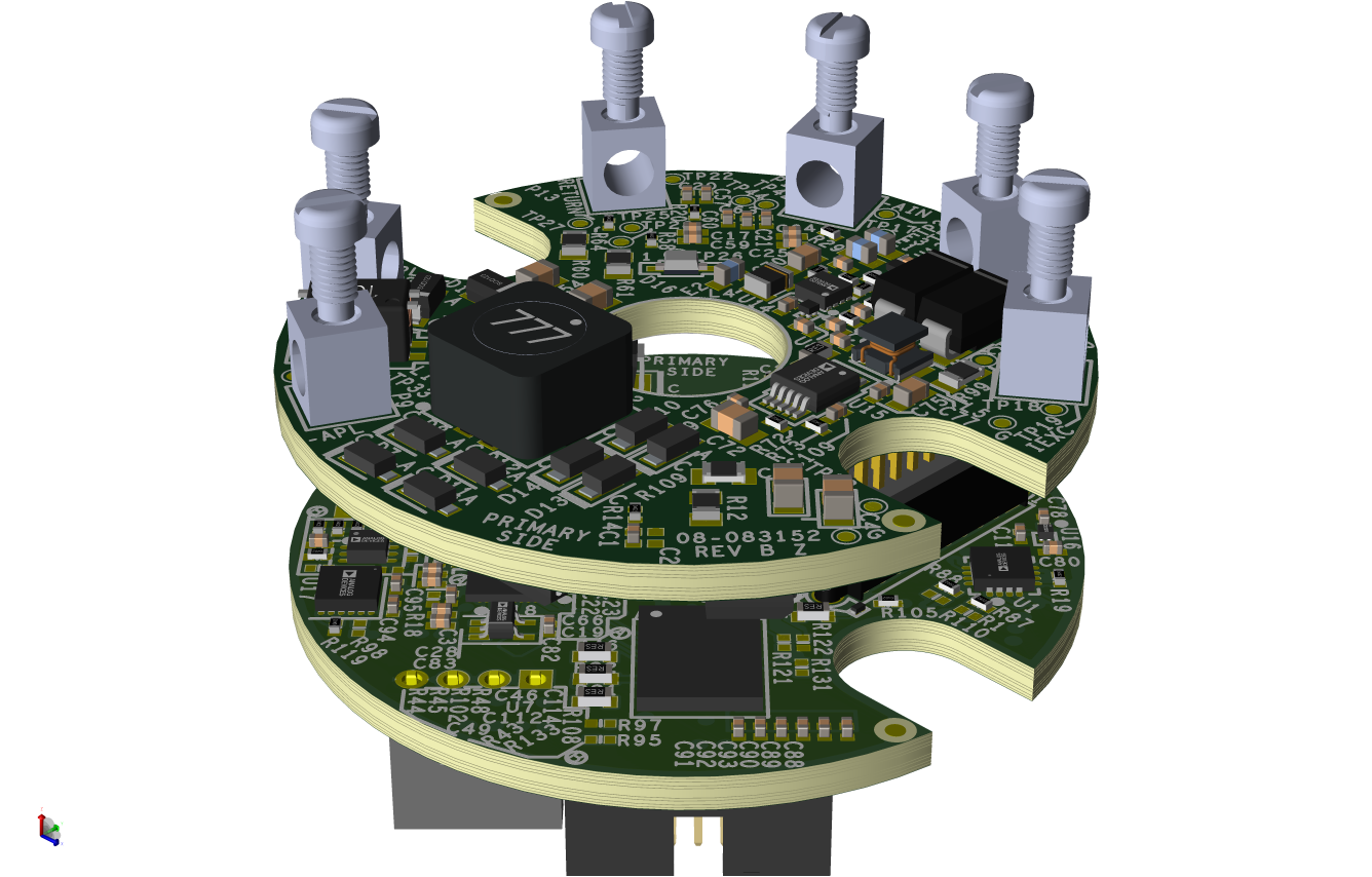
The AD-ETHERNETAPLDEVICE-SL is a complete Ethernet-APL field platform designed for prototyping intelligent, secure, and connected industrial field devices.
Key Features
Certified for intrinsic safety (Ex ia IIC Ga)
Pre-certified Ethernet-APL
Extensive security features: built-in security for hardware root-of-trust, data confidentiality and integrity, and secure communications.
Designed with IEC 62443 and EUCRA requirements in mind. Support available for security certification.
MAX42500 voltage monitor with integrated windowing watchdog
MAX6613 temperature sensor
ADFS7124-4 sigma-delta ADC (SC3 certified)
Complete FMEDA documentation
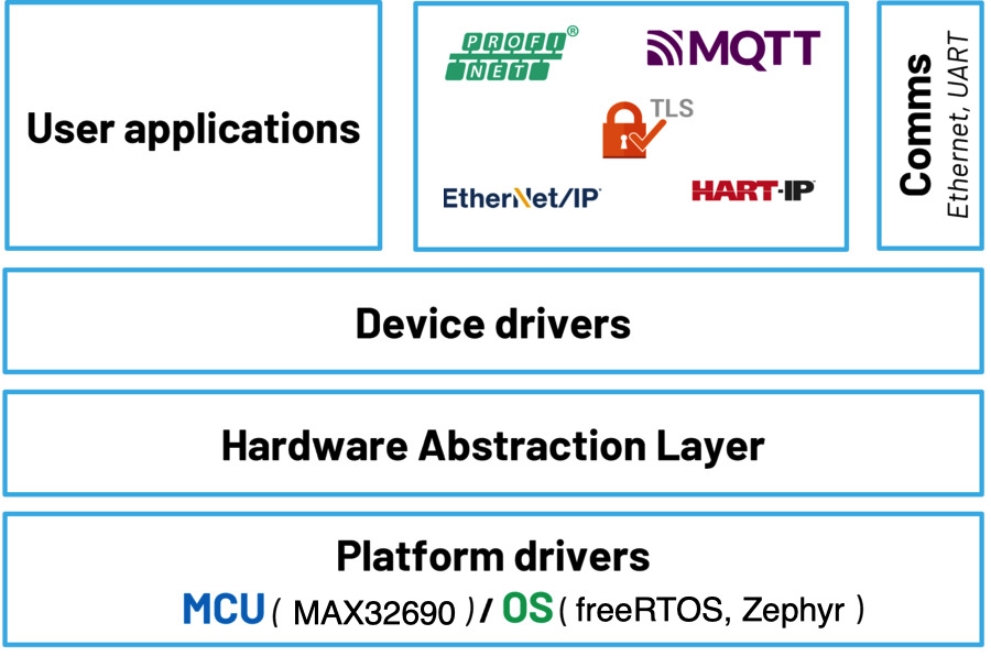
MAX32690 dual-core MCU (ARM Cortex-M4 with FPU + RISC-V co-processor)
External RAM (512 Mb) and Flash (64 Mb)
10BASE-T1L Ethernet via ADIN1110 MAC/PHY
Supports APL class A, ADIN1100D2Z recommended
Open-source software stack with drivers and example applications
Zephyr RTOS support and integration with Code Fusion Studio

Hardware Design Files
Download
The hardware design files are available for download from the product page. The design files include schematics, PCB layouts, and bill of materials (BOM) for the AD-EthernetAPLDevice-SL.
Package Contents
The development kit is delivered with a set of accessories required to put the system together and get it up and running in no time.
This is what you’ll find in the development kit box:
1x AD-EthernetAPLDevice-SL intrinsic safety certified kit (Power and Comms + Digital IS boards)
1x Digital NON-IS board. This board is not IS certified and enables access to the RISC-V Jtag for debugging purposes (Digital NON-IS board)
1x MAX32650PICO programmer (ARM) + cable
1x Olimex programmer (RISC-V)
1x Olimex adapter + cable
Application Development
The AD-ETHERNETAPLDEVICE-SL firmware examples are based on ADI’s open-source no-OS framework. It includes the bare-metal device drivers for all the components in the system as well as example applications enabling connectivity via the 10BASE-T1L interface for system configuration and data transfer.
Additionally, a proprietary PROFINET stack software application is available to enable easy evaluation and system prototyping (MyAnalog account required).
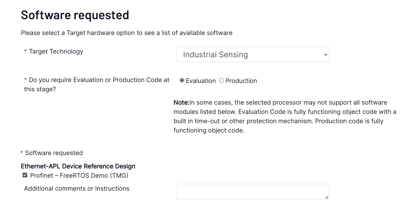
Software Request
To request for the software package, please accomplish this form: https://form.analog.com/form_pages/softwaremodules/SRF.aspx
Under Target Technology, please select Industrial Sensing
and check the box for Ethernet-APL Device Reference Design/Profinet - FreeRTOS Demo (TMG).
Hardware Components and Connections
Hardware Setup
Required Hardware
Development kit: AD-EthernetAPLDevice-SL
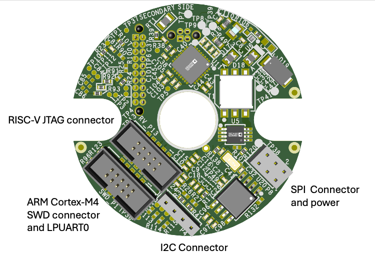
Debugging board: If RISC-V co-processor needs to be debugged, replace the IS digital board with the NON-IS Digital board
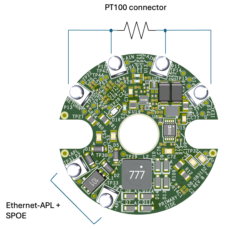
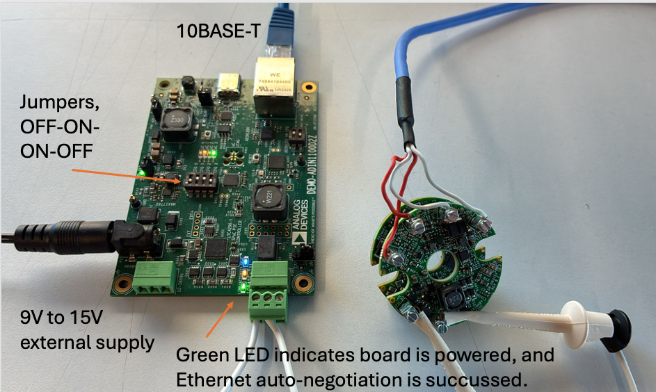
Power supply: Powered via DEMO-ADIN1100D2Z supplied from external power connector (from 9V to 15V), or an Ethernet-APL field switch
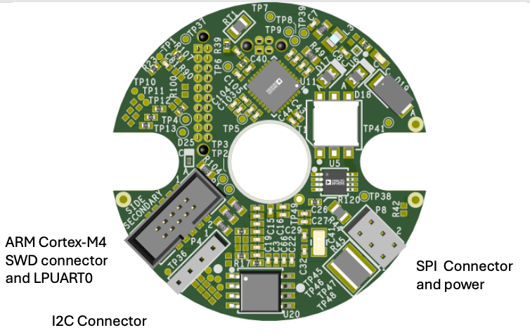
ARM programmer: MAX32625PICO or any SWD-compatible programmer
RISC-V programmer: Olimex ARM-USB-OCD
Media converter: 10BASE-T1L to 10BASE-T or similar. DEMO-ADIN1100D2Z includes a media converter and can be used for both power and data, or an Ethernet-APL field switch
Setup Instructions
Connect the AD-EthernetAPLDevice-SL to the DEMO-ADIN1100D2Z and ensure all connectors are fully seated.
Connect a 2- or 4-wire PT100 sensor to the temperature connector.
Attach the MAX32625PICO programmer to the ARM debug header using the 10-pin ribbon cable.
For RISC-V debugging, install the NON-IS digital board and connect the RISC-V debug probe to the RISC-V Jtag header (available only on the NON-IS board).
Connect the DEMO-ADIN1100D2Z to your PC via Ethernet.
Apply power to the DEMO-ADIN1100D2Z (9V to 15V input). The AD-EthernetAPLDevice-SL will be powered via Ethernet.
Software Setup
Programming the AD-EthernetAPLDevice-SL
The AD-EthernetAPLDevice-SL is supported by an open-source software stack based on Analog Devices’ no-OS framework. It includes:
Baremetal drivers for all on-board components
Example applications for data acquisition and system configuration via 10BASE-T1L
Zephyr RTOS board definition
Integration with Code Fusion Studio
For a complete experience, download latest Code Fusion Studio from here.
The software stack includes:
no-OS drivers and HAL
Example applications for ADCs, DACs, sensors
UART and Ethernet (10BASE-T1L) communication support
Zephyr RTOS support
Complementary Documentation
Help and Support
For questions and more information, please visit the EngineerZone community or contact your local ADI representative.