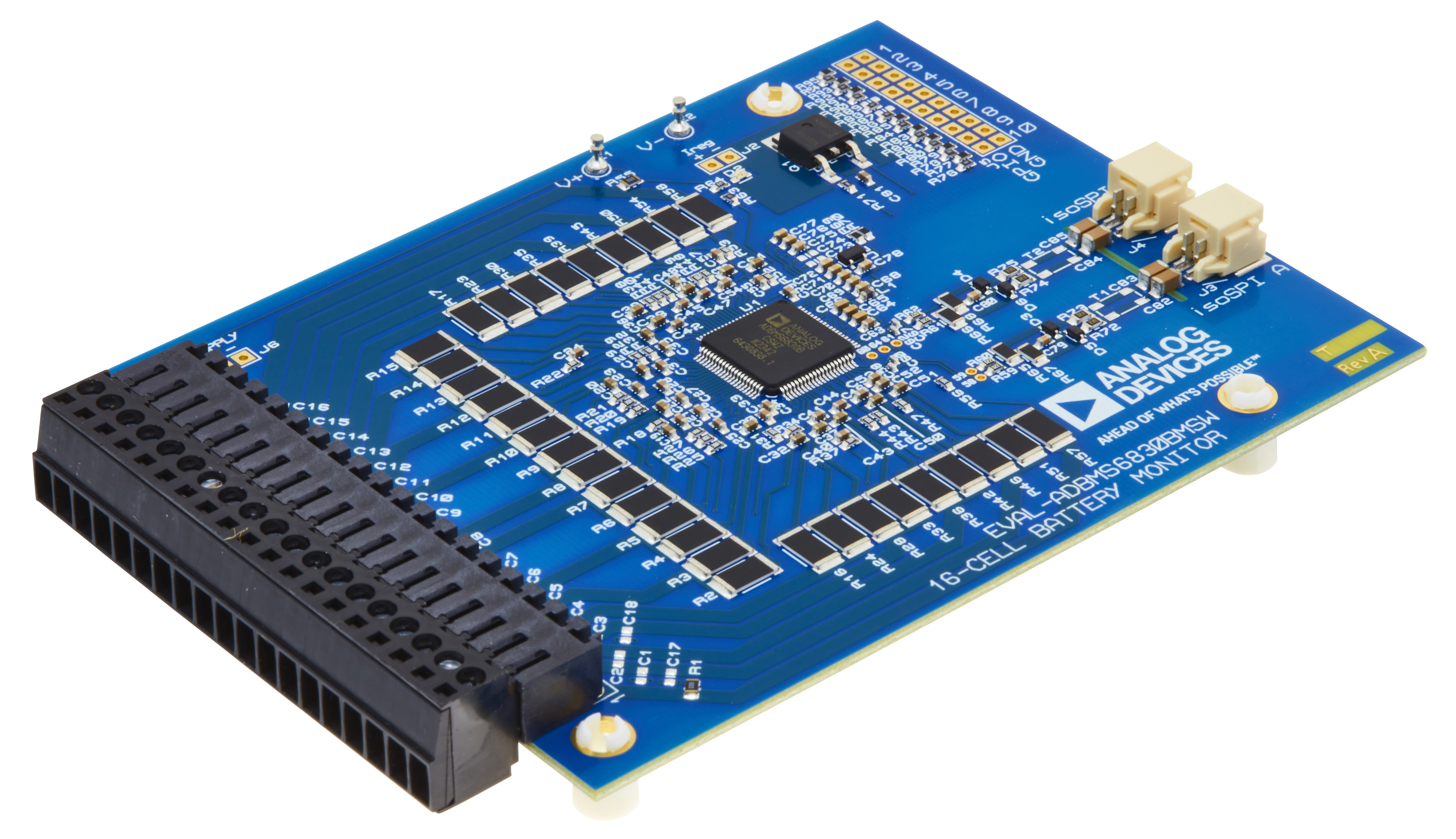
EVAL-ADBMS6830BMSW
16-Channel Battery Stack Monitor Evaluation Board for Broad Market Applications.
Overview
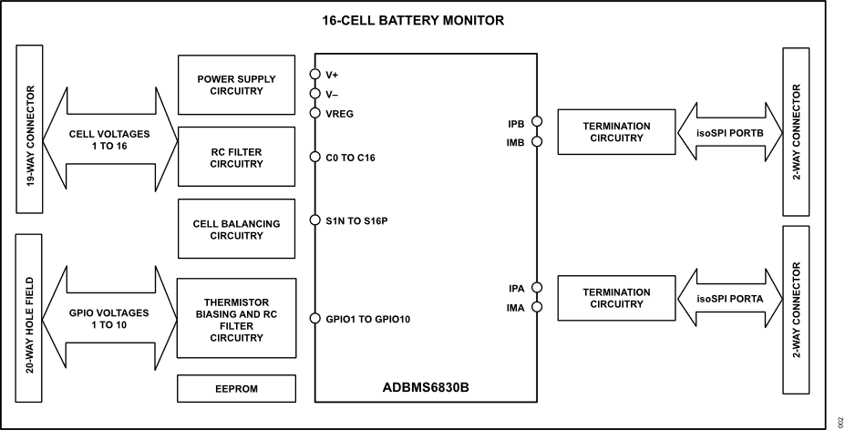
The EVAL-ADBMS6830BMSW is a full-featured evaluation board for the ADBMS6830B, a 16-channel battery stack monitor for broad market applications. This board allows multiple boards to be linked through a single, twisted pair wire interface (isoSPI) to monitor a long series of cells in a stack. It provides access to full channel monitoring to all cells going to battery pack either in the supply line or in the V+ to V- line. The evaluation board also features reversible isoSPi that can access either path to do measurement functions and serve as a redundant communication path. The PCB, components, and DuraClik connectors are optimized for low EMI susceptibility and emissions.
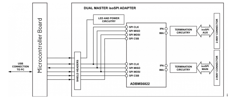
The EVAL-ADBMS6830BMSW can communicate to a PC by connecting an EVAL-ADBMS6822 dual master isoSPI together with a microcontroller board such as the EVAL-SDP-CK1Z, the AD-APARD32690-SL, or the MAX32670EVKIT.
The SDP-K1 and the other MCUs mentioned above provide a standard SPI interface, which can be translated to isoSPI port (J3 or J4 connector). A separate EVAL-ADBMS6822 companion board provides two SPI-to-isoSPI channels for reversible operation.
Features
Full featured evaluation board for the ADBMS6830B
Demonstrates high-performance measurements of the ADBMS6830B
Includes two isoSPI ports for reversible isoSPI support
Daisy-chain capability
Accessible cell and GPIO connections via optional connectors
Accessible isoSPI connections via simple DuraClik connectors
Compatible with EVAL-ADBMS6822 dual master isoSPI board
With PC-based software for control and data analysis using the Broad Market Browser BMS GUI
Basic embedded code functions for cell monitoring and diagnostics
Applications
Mobile Robot System
E-scooter/E-bikes/Light Electric Vehicle
Agricultural Gateway Hubs
Metering Technology
Power Tools
Portable Energy Storage System
Industrial Equipment Battery Monitoring
System Architecture
Hardware Setup
Equipment Needed
EVAL-ADBMS6822 dual master isoSPI adapter board
EVAL-SDP-CK1Z or AD-APARD32690-SL microcontroller board
DC2472A Battery Stack Simulator
isoSPI DuraClik connectors
USB cable
Host PC with installed Broadmarket BMS Software
Cell Voltage Connection (J1)
Important
Correct wiring must be followed to avoid the risk of damaging the EVAL-ADBMS6830BMSW evaluation board.
When connected to a battery stack, the cell group being monitored provides power for the EVAL-ADBMS6830BMSW.
To connect the cell group, separate the screw-terminal block section from the J1 connector.
Insert the cell voltage connections or resistors into the screw-terminal clamping contacts. These connections provide power and input stimuli for the battery stack monitor IC.
The cell voltages are wired to J1, starting from position 1 (the most negative potential of the group). See Table 1 for the correct J1 pinout.
Table 1. Pin Designations for J1 Connector |
|
|---|---|
Pin No. |
Connection |
1 |
C0 (stack-) |
2 |
C1 |
3 |
C2 |
4 |
C3 |
5 |
C4 |
6 |
C5 |
7 |
C6 |
8 |
C7 |
9 |
C8 |
10 |
C9 |
11 |
C10 |
12 |
C11 |
13 |
C12 |
14 |
C13 |
15 |
C14 |
16, 17 |
C15, C16 (stack+) |
Tip
Alternatively, resistors can be used to simulate battery cell voltages. 100 Ω ½ W or equivalent resistors are recommended because 100 Ω (or lower values) typically will not induce measurement errors, and the ½ W (or greater rating) will keep the resistor temperatures low, preventing power dissipation damage.
Resistors Connection
Carefully connect 16 100 Ω resistors into the screw-terminal block between each CPIN input clamping contact from position 1 to position 17, EVAL-ADBMS6830BMSW J1 pinout, and the resistor divider string.
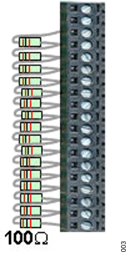
Provide a stack equivalent power supply connection to position 17 (positive) and position 1 (negative).
Adjust power supply to provide the desired nominal cell voltage (for example, 52.8V will be 3.3V per cell).
Serial Interface Connection
isoSPI is the only communication option for the EVAL-ADBMS6830BMSW. Due to the custom EMI-optimized isoSPI cable with DuraClik connectors, it is highly recommended to use the EVAL-ADBMS6822 dual master isoSPI demo board or equivalent for easy plug-and-play operation.
The EVAL-ADBMS6822 dual master isoSPI demo board can be connected as a typical single-ended isoSPI bus master or to both ends of a reversible configuration with two isoSPI bus masters.
Optional Connections
GPIO Optional Header (J5)
This double row of thru-holes (hole field) can be used as test points for GPIO voltages or can be wired with individual V-/GND connections with connections with each GPIO.
Table 2. Pin Designations for J5 Connector |
|
|---|---|
Pin No. |
Connection |
1 |
GPIO1 |
2 |
GPIO2 |
3 |
GPIO3 |
4 |
GPIO4 |
5 |
GPIO5 |
6 |
GPIO6 |
7 |
GPIO7 |
8 |
GPIO8 |
9 |
GPIO9 |
10 |
GPIO10 |
11 |
V- |
12 |
V- |
13 |
V- |
14, 15, 16, 17, 18, 19, 20 |
V-, V-, V-, V-, V-, V- |
IREG Optional Header (J2)
This pair of thru-holes can be used to measure IREG with an ammeter. The use of an ammeter bypasses the D2 LED (VREG active), which allows accurate measurement of IREG current.
Add an ammeter between J2 pins 1 and 2 to measure IREG.
Supply Optional Header (J6)
This pair of thru-holes can be used to insert and measure the supplied voltage with a power supply or voltmeter, respectively.
To furnish power separately from the cell stack, remove R55 and the power board using J6.
General Setup
Important
To prevent damage to the EVAL-ADBMS6830BMSW, see Table 1 to confirm that the cell voltage connections to the screw-terminal block matches the EVAL-ADBMS6830BMSW J1 pinout.
The 2-wire twisted pair cable with the DuraClik end plugs have 1 mm thick locking tabs on the wiring side that must be pressed down to release from the DuraClik receptacles. Failure to do so may damage the cable and prevent board-to-board isoSPI communication.
EVAL-ADBMS6822 to EVAL-ADBMS6830BMSW Typical isoSPI Connection
Tip
This setup uses the SDP-K1 as microcontroller, but users may also use the AD-APARD32690-SL as MCU and follow the same setup presented below.
A typical isoSPI connection begins with the isoSPI master connected to the first (or bottom) EVAL-ADBMS6830BMSW. Additional EVAL-ADBMS6830BMSW boards can be daisy-chained onto the isoSPI bus. Communication begins with the first (or bottom) EVAL-ADBMS6830BMSW, then to the next upper EVAL-ADBMS6830BMSW, and finally to the last (or top) EVAL-ADBMS6830BMSW.
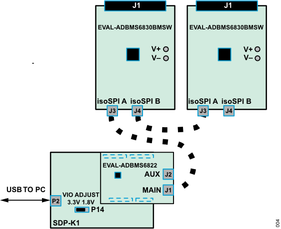
Figure 5 EVAL-ADBMS6822 to EVAL-ADBMS6830BMSW Typical isoSPI Connection
Connect the EVAL-ADBMS6822 dual master isoSPI demo board to the EVAL-SDP-CK1Z through the shield headers.
Set the P14 jumper of the SDP-K1 to the 3.3 V position.
Connect a USB cable from the PC USB port to the SDP-K1 P2 connector.
Connect the EVAL-ADBMS6822 (J1) to the EVAL-ADBMS6830BMSW (J3) using the 2-wire twisted-pair patch cable from the main DuraClik connector to isoSPI A DuraClik connector.
Connect or daisy-chain the EVAL-ADBMS6830BMSW to the other EVAL-ADBMS6830BMSW in isoSPI mode. This EVAL-ADBMS6830BMSW is the last (or top) board in the stack. More EVAL-ADBMS6830BMSW can be daisy-chained in the same manner.
Connect a 2-wire twisted pair patch cable from the bottom EVAL-ADBMS6830BMSW (J4) isoSPI DuraClik connector to the upper board.
Plug the screw-terminal block(s) into the J1 cell voltage connectors.
Download
A Windows-based graphical user interface is available for users to readily evaluate this system.
For Software Setup instructions, visit the EVAL-ADBMS6830BMSW Software User Guide
EVAL-ADBMS6822 to EVAL-ADBMS6830BMSW Reverse isoSPI Connection
Tip
This setup uses the SDP-K1 as microcontroller, but users may also use the AD-APARD32690-SL as MCU and follow the same connection procedure presented below.
A reverse isoSPI connection begins with the isoSPI master connected to the last (or top) EVAL-ADBMS6830BMSW. Additional EVAL-ADBMS6830BMSW boards can be daisy-chained onto the isoSPI bus. Communication begins from the last (or top) EVAL-ADBMS6830BMSW, then to the next lower EVAL-ADBMS6830BMSW, and finally to the first (or bottom) EVAL-ADBMS6830BMSW.
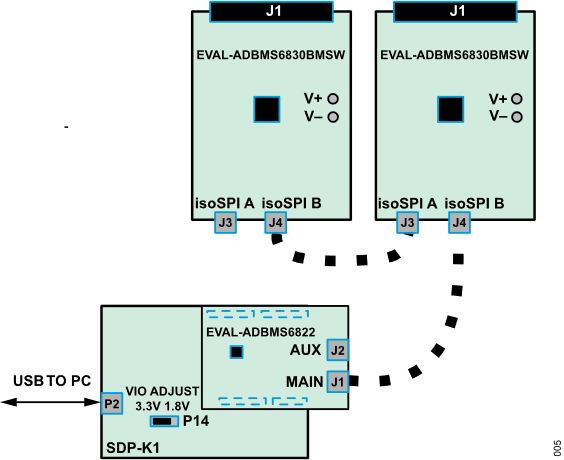
Figure 6 EVAL-ADBMS6822 to EVAL-ADBMS6830BMSW Reverse isoSPI Connection
Connect the EVAL-ADBMS6822 dual master isoSPI demo board to the EVAL-SDP-CK1Z through the shield headers.
Set the P14 jumper of the SDP-K1 to the 3.3 V position.
Connect a USB cable from the PC USB port to the SDP-K1 P2 connector.
Connect the EVAL-ADBMS6822 (J1) to the EVAL-ADBMS6830BMSW (J4) using the 2-wire twisted-pair patch cable from the main DuraClik connector to isoSPI B DuraClik connector.
Connect or daisy-chain the EVAL-ADBMS6830BMSW to the other EVAL-ADBMS6830BMSW in isoSPI mode. This EVAL-ADBMS6830BMSW is the first (or bottom) board in the stack. More EVAL-ADBMS6830BMSW lower boards can be daisy-chained in the same manner.
Connect a 2-wire twisted pair patch cable from the top EVAL-ADBMS6830BMSW (J3) isoSPI A DuraClik connector to the next lower (or bottom) EVAL-ADBMS6830BMSW board (J4) isoSPI B DuraClik connector.
Plug the screw-terminal block(s) into the J1 cell voltage connectors.
EVAL-ADBMS6822 to EVAL-ADBMS6830BMSW Redundant isoSPI Connection
Tip
This setup uses the SDP-K1 as microcontroller, but users may also use the AD-APARD32690-SL as MCU and follow the same setup presented below.
A redundant isoSPI connection begins with the primary (or main) isoSPI master connected to the first (or bottom) EVAL-ADBMS6830BMSW and has a backup auxiliary isoSPI master connected to the last (or top) EVAL-ADBMS6830BMSW.
Additional EVAL-ADBMS6830BMSW boards can be daisy-chained between the two isoSPI masters on the isoSPI bus. Primary (or main) communication begins with the first (or bottom) EVAL-ADBMS6830BMSW then to the upper EVAL-ADBMS6830BMSW and finally, to the last (or top) EVAL-ADBMS6830BMSW. The backup auxiliary communication begins in the reverse direction to provide coverage when a possible isoSPI daisy-chain break occurs.
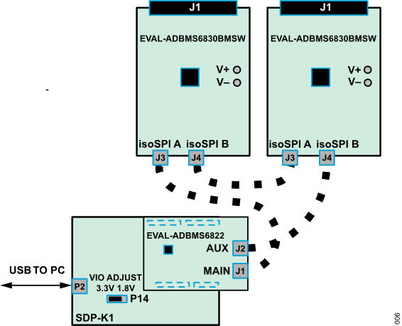
Figure 7 EVAL-ADBMS6822 to EVAL-ADBMS6830BMSW Redundant isoSPI Connection
Connect the EVAL-ADBMS6822 dual master isoSPI demo board to the EVAL-SDP-CK1Z through the shield headers.
Set the P14 jumper of the SDP-K1 to the 3.3 V position.
Connect a USB cable from the PC USB port to the SDP-K1 P2 connector.
Connect the EVAL-ADBMS6822 primary isoSPI master to the first EVAL-ADBMS6830BMSW board in the stack.
Connect 2-wire twisted-pair patch cable from the EVAL-ADBMS6822 (J1) main DuraClik connector to the first EVAL-ADBMS6830BMSW (J3) isoSPI A DuraClik connector.
Connect or daisy-chain the EVAL-ADBMS6830BMSW to the other EVAL-ADBMS6830BMSW in isoSPI mode. This EVAL-ADBMS6830BMSW is the last (or top) board in the stack. More EVAL-ADBMS6830BMSW can be daisy-chained in the same manner.
Connect a 2-wire twisted pair patch cable from the bottom EVAL-ADBMS6830BMSW (J4) isoSPI B DuraClik connector to the upper EVAL-ADBMS6830BMSW board (J3) isoSPI A DuraClik connector.
Connect the EVAL-ADBMS6822 auxiliary isoSPI master to the last (or top) EVAL-ADBMS6830BMSW board in the stack.
Connect a 2-wire twisted pair patch cable from the EVAL-ADBMS6822 (J2) auxiliary DuraClik connector to the top EVAL-ADBMS6830BMSW (J4) isoSPI B DuraClik connector.
Plug the screw-terminal block(s) into the J1 cell voltage connectors.
Resources
User Guides
A Software User Guide is available.
Design & Integration Files
Download
EVAL-ADBMS6830BMSW Design Support Package
Schematic
PCB Layout
Bill of Materials
Allegro Project
Help and Support
For questions and more information about this product, connect with us through the Analog Devices EngineerZone.