EVAL-ADRV902X
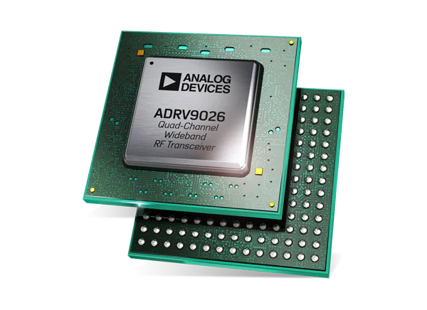
Integrated, Quad RF Transceiver with Observation Path.
Overview
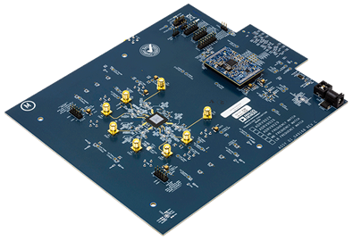
The EVAL-ADRV9026/ADRV9029, are FMC radio cards designed to showcase the ADRV9026 and ADRV9029, highly integrated, radio frequency (RF) agile transceivers offering 4 independently controlled transmitters, dedicated observation receiver inputs for monitoring each transmitter channel, 4 independently controlled receivers, integrated synthesizers, and digital signal processing functions providing complete transceiver solutions.
The devices provide the performance demanded by cellular infrastructure applications, such as small cell base station radios, macro 3G/4G/5G systems, and massive multiple in/multiple out (MIMO) base stations.
Features:
Both chips feature:
4 differential transmitters & 4 differential receivers
2 observation receivers with 2 inputs each
Support for TDD and FDD applications
24.33 Gbps JESD204B/JESD204C digital interface
Complete ADRV9026 radio cards for evaluation
ADRV9026-HB/PCBZ for frequency band 2.8GHz to 6GHz
ADRV9026-MB/PCBZ for frequency band 650MHz to 2.8GHz
ADRV9026-LB/PCBZ for frequency band 75MHz to 1000MHz
Complete ADRV9029 radio cards for evaluation
ADRV9029-HB/PCBZ (integrated DPD & CFR) for frequency band 2.8GHz to 6GHz
ADRV9029-MB/PCBZ (integrated DPD & CFR) for frequency band 650MHz to 2.8GHz
A separate power daughter card provides reference design for high efficiency power supply solution
FMC connector for FPGA
Applications:
3G/4G/5G TDD and FDD massive MIMO, macro and small cell base stations
Recommendations
People who follow the flow that is outlined, have a much better experience with things. However, like many things, documentation is never as complete as it should be. If you have any questions, feel free to ask on our EngineerZone forums, but before that, please make sure you read our documentation thoroughly.
To better understand the ADRV9026 / ADRV9029, we recommend to use the EVAL-ADRV9026/ADRV9029 evaluation board.
Table of contents
Using the evaluation board/full stack reference design that we offer:
Prerequisites - what you need to get started
-
Using the VCK190/Versal
Using the ZCU102/Zynq UltraScale+ MP SoC
Configure an SD Card with Kuiper
Linux Applications
Design with the ADRV9026/ADRV9029
Hardware in the Loop / How to design your own custom BaseBand
Resources for designing a custom ADRV9026/ADRV9029-based platform software
For Linux software:
About the device driver:
About the device tree:
About the JESD204 utilities:
Changing the VCXO frequency and updating the default RF Transceiver Profile
HDL reference design which you must use in your FPGA.
Additional documentation about SDR Signal Chains - The math behind the RF
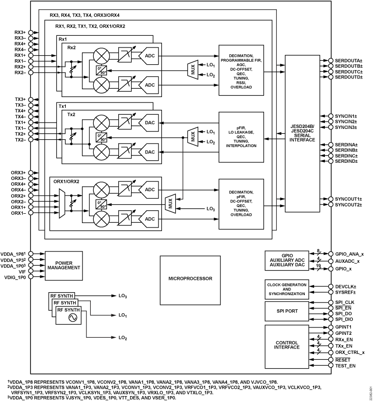
Block diagram
Videos
Software Defined Radio using the Linux IIO Framework
ADI articles
Four Quick Steps to Production: Using Model-Based Design for Software-Defined Radio:
Part 2 - Mode S Detection and Decoding Using MATLAB and Simulink
Part 3 - Mode S Signals Decoding Algorithm Validation Using Hardware in the Loop
Part 4 - Rapid Prototyping Using the Zynq SDR Kit and Simulink Code Generation Workflow
About JESD standard:
MathWorks webinars
Additional information
Digital Pre-Distortion (DPD) User Guide with the ADRV9029:
Warning
All the products described on this page include ESD (electrostatic discharge) sensitive devices. Electrostatic charges as high as 4000V readily accumulate on the human body or test equipment and can discharge without detection. Although the boards feature ESD protection circuitry, permanent damage may occur on devices subjected to high-energy electrostatic discharges. Therefore, proper ESD precautions are recommended to avoid performance degradation or loss of functionality. This includes removing static charge on external equipment, cables, or antennas before connecting to the device.