EVAL-LTPA-KIT Hardware User Guide
The EVAL-LTPA-KIT or LTpowerAnalyzer™ Kit is a low-cost, high performance, compact laboratory tool for evaluating and characterizing power supply designs – allowing measurements of frequency response, transient response, and output impedance. Combined with the capabilities of the ADALM2000 Learning Module, it offers high portability with its compact size.
The LTpowerAnalyzer™ Software offers a user-friendly interface with documentations for ease of usage. It comes with four different current probes for 1A, 10A, 50A, and 100A. Immediately kick-off using the kit with the LT8642S-based demo board as the device under test (DUT).
Hardware Setup
Equipment Needed
The EVAL-LTPA-KIT comes with the following boards and accessories:
Base Board:
LTpowerAnalyzer™ Base Board
Current Probes:
1A Current Probe
10A Current Probe
50A Current Probe
100A Current Probe
Interposer Boards:
Interface Connector Board A
Interface Connector Board B (5 pieces)
Interface Connector Board C
LT8642A Demo Board (DUT)
2-Inch 16-Pin Ribbon Cable
8-Inch 14-Pin Ribbon Cable
Connector Sockets (2 pieces)
The following list of equipment are not provided as part of the kit, but are required for running the setup described in this guide.
Laptop or PC running Windows 10
Digital power supply (12V)
Bode Plot Measurement
The Bode Plot measurement scheme works by injecting a voltage signal to the feedback network. As discussed in the Components and Connections section, depending on the feedback network of the DUT, this may be done by placing a series injection resistor.
The included DUT, LT8642S Demo Board, features a 16-pin male header for easy interfacing with the LTpowerAnalyzer™’s interposer board. The demo board may be connected to the interface board of the LTpowerAnalyzer™ via a ribbon cable.
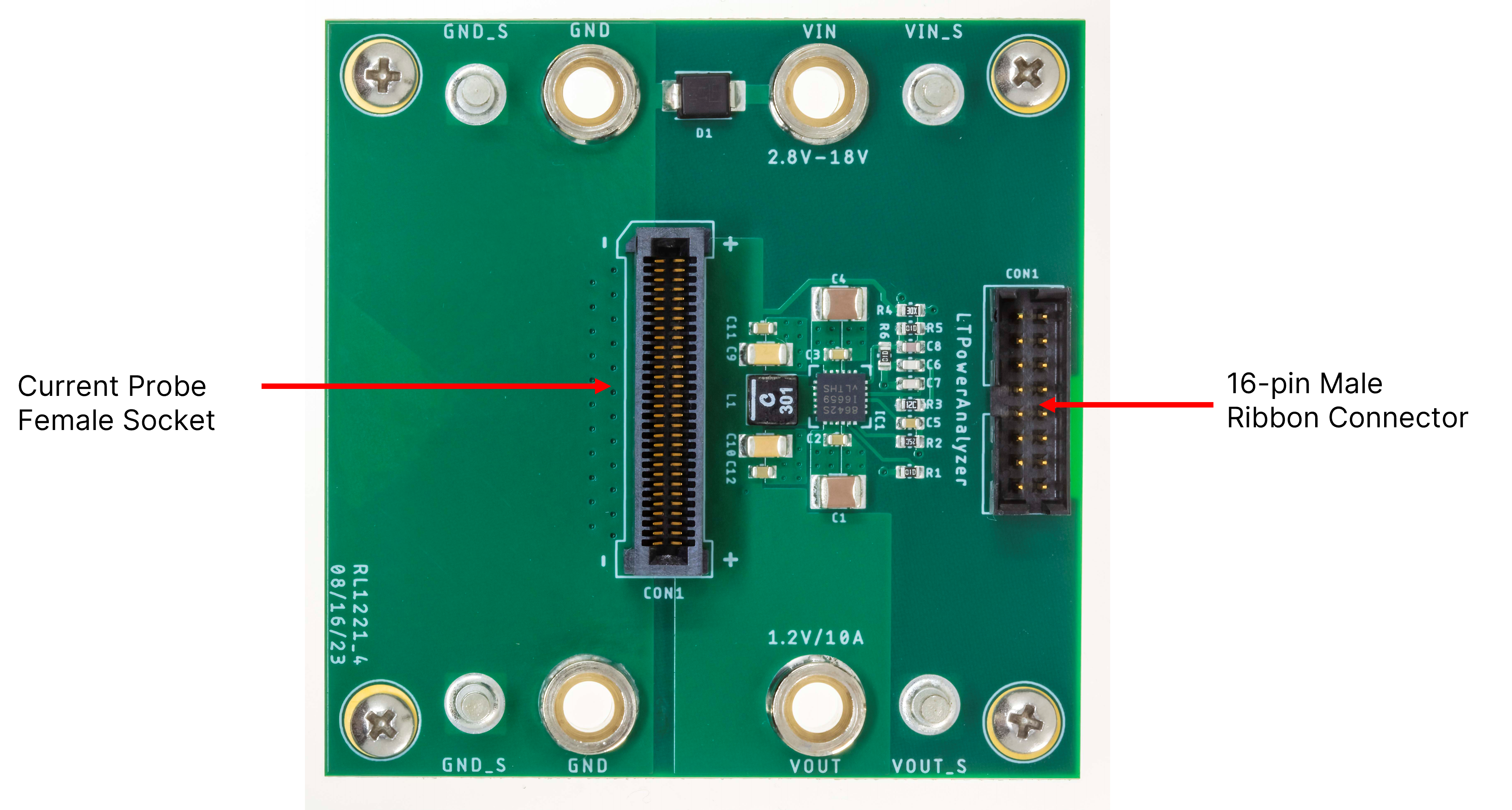
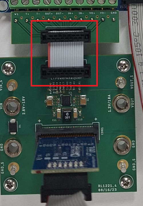
Figure 2 Sample ribbon cable connection from the Demo Board to the LTpowerAnalyzer™ (via the Interface A Board)
However, other DUTs do not have a native support for these interfaces. Below is an example illustrating how to set up the hardware DUT for gain and phase measurements.
Note
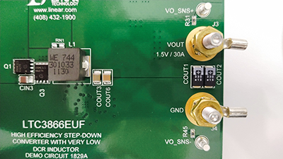
A DC1516A-B demo board, featuring the LTC3833EFE controller, was used to demonstrate simple hardware modifications to make a Bode Plot Measurement with any DUT without the native socket connectors.
1. Identifying where to connect the injection signal
Determine which connection type is appropriate for your circuit as described in the Components and Connections section. Consult the data sheet or schematic diagram of the DUT.
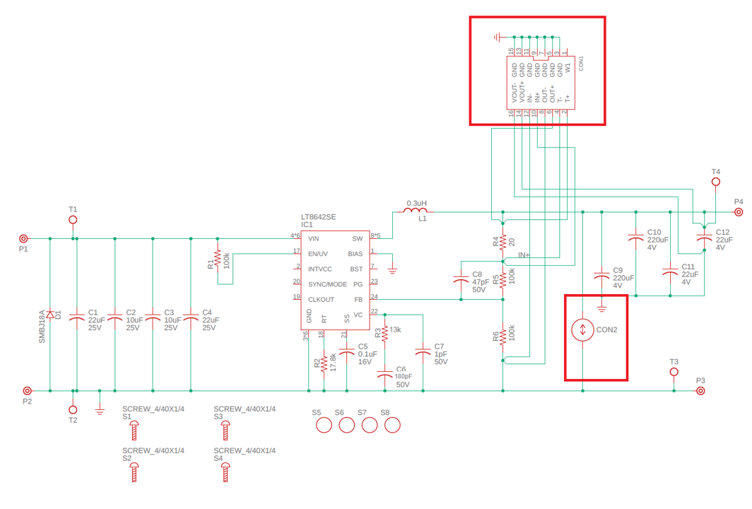
This DC1516A-B Demo Board already has a 10Ω injection resistor in series with the feedback network as shown below:
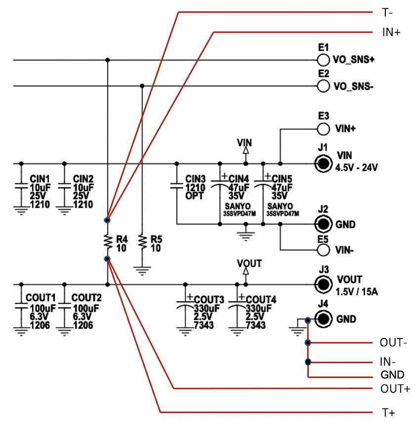
For this example, choose the kelvin connection setup with the transformer (T+ & T-) and the signal inputs (OUT+ & IN+) terminal block pins connected to the injection resistor R4. Connect the OUT-, IN-, and GND terminal block pins to the GND of the demo board. Most boards require adding the injection resistor before making the connections.
2. Soldering wires to the DUT
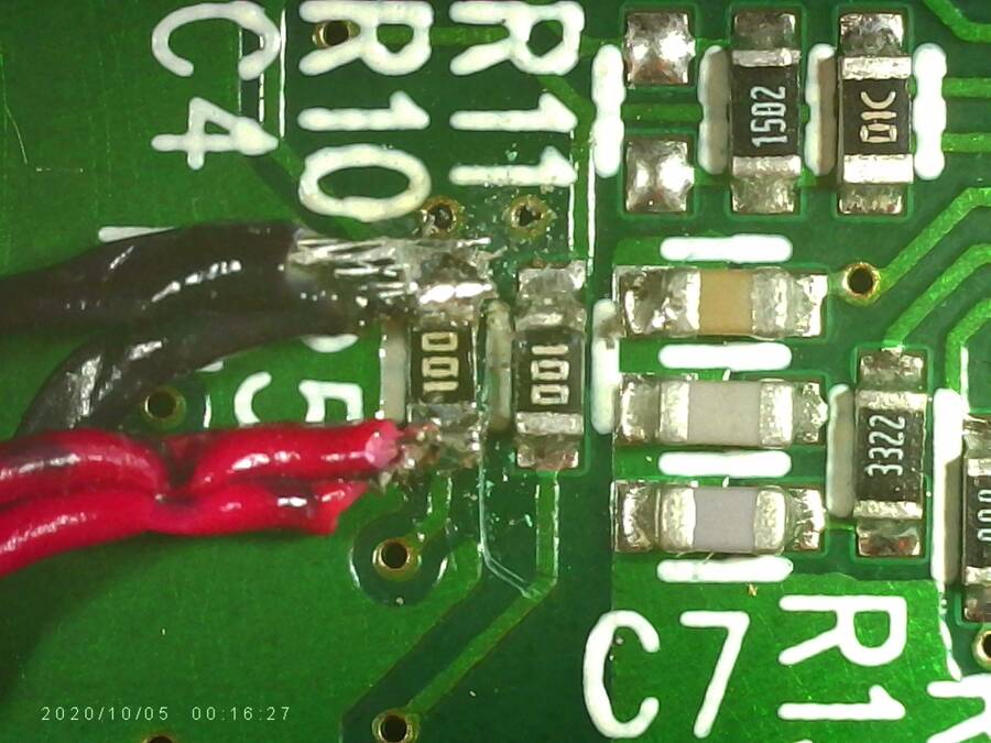
In this example, 28-gauge twisted pair wires (Red and Black), and a 26-gauge solid core wire were used for the connections.
Connect OUT+ and T+ together (Red Wire) to one of the terminals of the injection resistor.
Connect IN+ and T- together (Black Wire) to the opposite terminal of the injection resistor.
Connect all GND, OUT-, and IN- together to the ground plane of the DUT.
It is recommended to connect the OUT+ and T+ wires to the terminal connected directly to the DUT’s voltage output plane (VOUT). Recheck connections, and ensure there are no shorts.
3. Preparing the system for measurements
Connect the LTpowerAnalyzer™ (LB3031A) main board to the ADALM2000 (M2k) or the Analog Discovery 2 USB scope.
Connect the wires to the terminal block on the LTpowerAnalyzer™ main board and connect the demo board Vin inputs to a power supply.
Connect the USB scope to the computer via the USB cable and launch the LTpowerAnalyzer™ software.
Connect a current probe to the LTpowerAnalyzer™ main board.
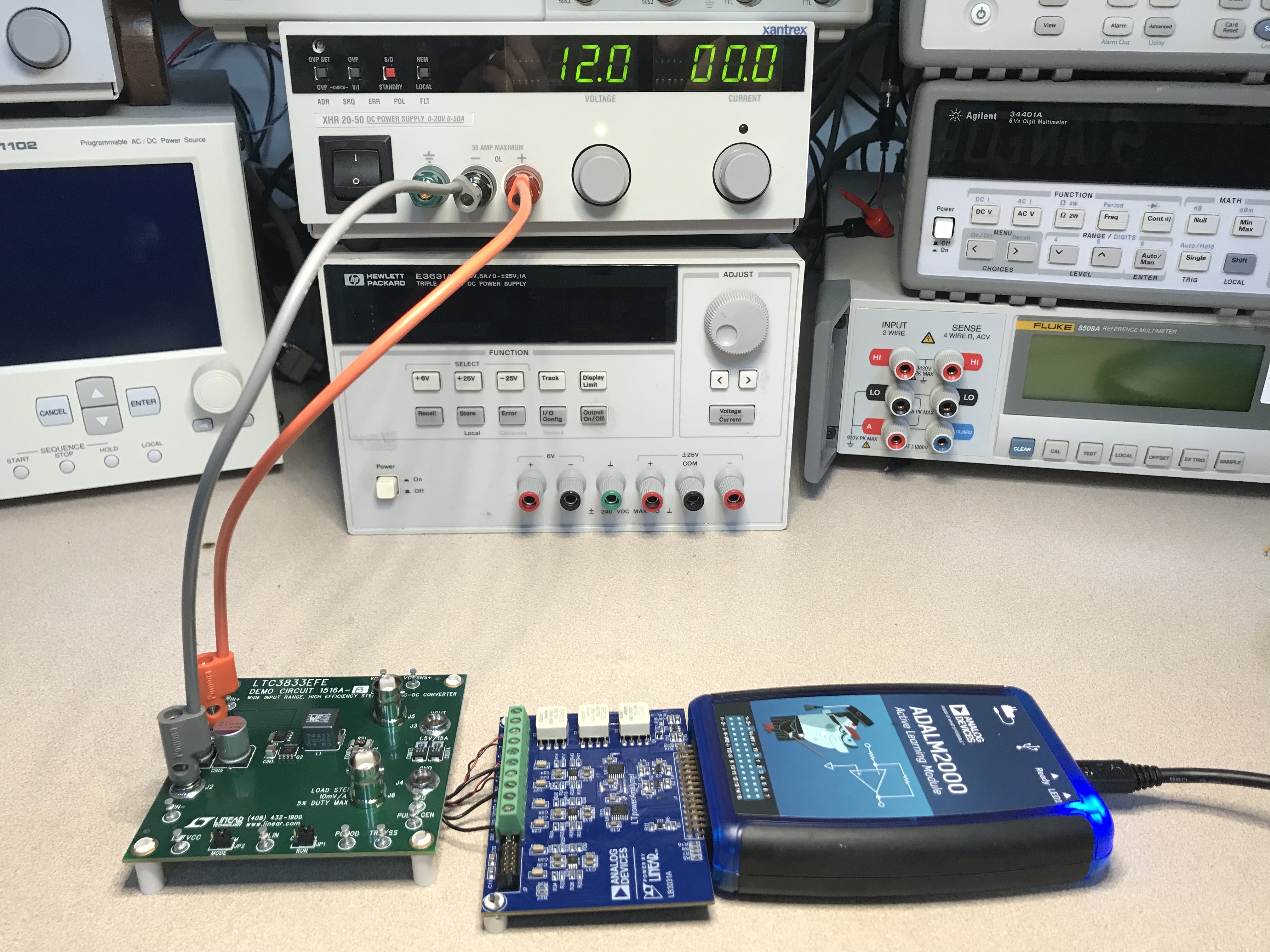
Figure 6 Basic LTpowerAnalyzer™ System Setup for Bode Plots Only (No current probe attached yet)
Transients and Impedance Measurements
Different methods of setting up a DUT for transients and impedance measurements:
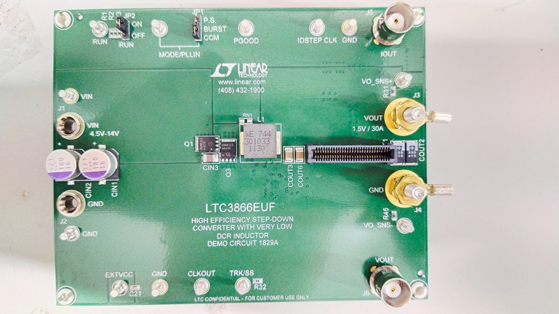
Method 1: LT8642S DUT
The out-of-the box DUT, LT8642S, comes with a readily installed female socket connector. This allows convenient changing of current probes, with no soldering required
Method 2: Soldering Braid Method
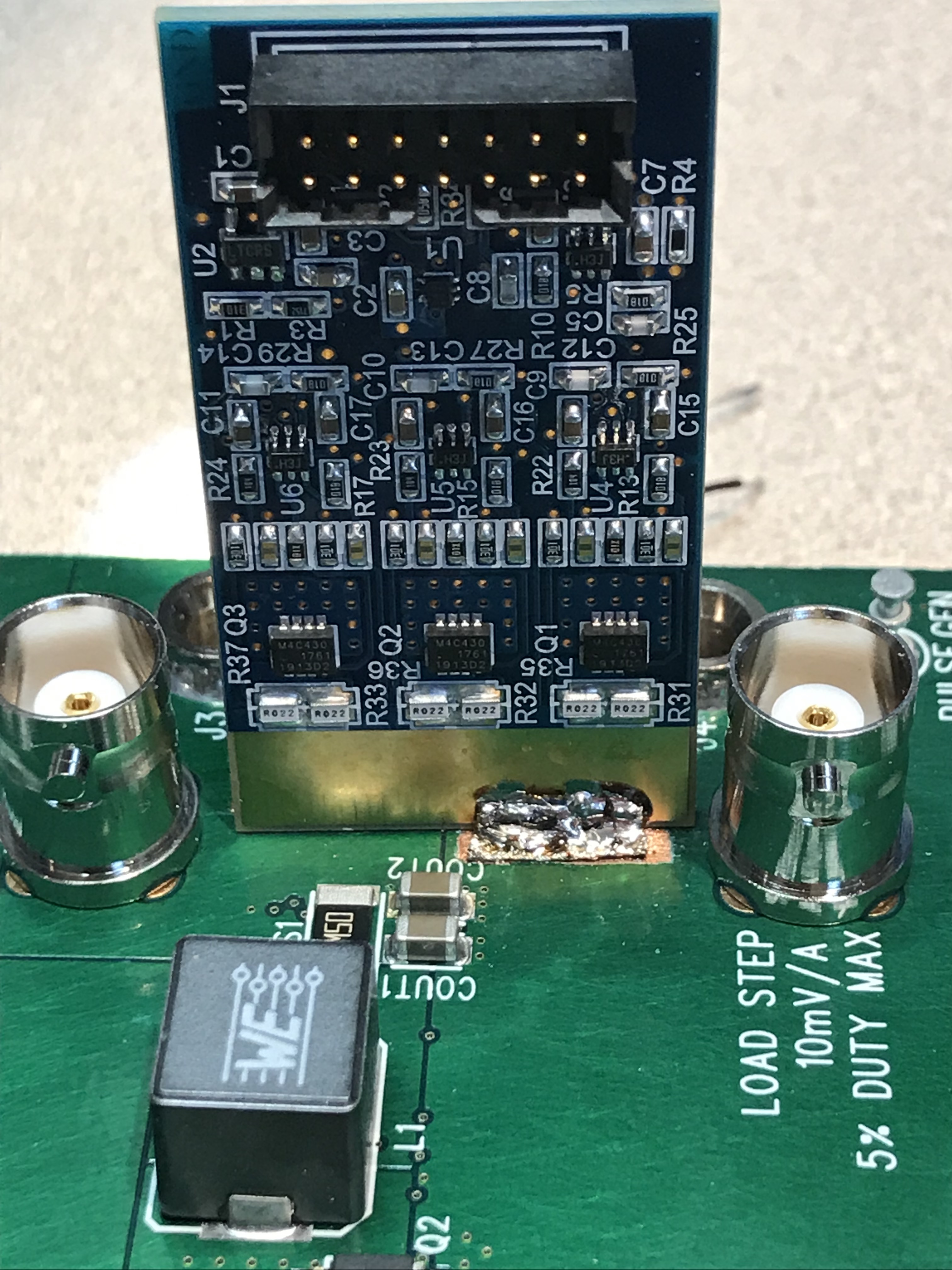
In this method, the LB3058A current probe will be directly installed at the DUT via soldering braids for a good mechanical connection.
This method improves electrical connection by reducing parasitics from affecting the measurements and providing a good mechanical connection. However, its biggest drawback is that the DUT is damaged due to the scraping of the solder mask, thus making it challenging to swap current probes.
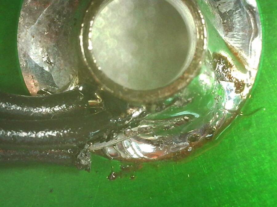
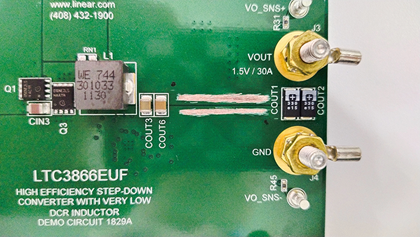
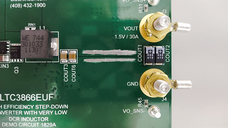
1. Scrape off the solder mask on the GND and VOUT planes, then add folded solder braid.
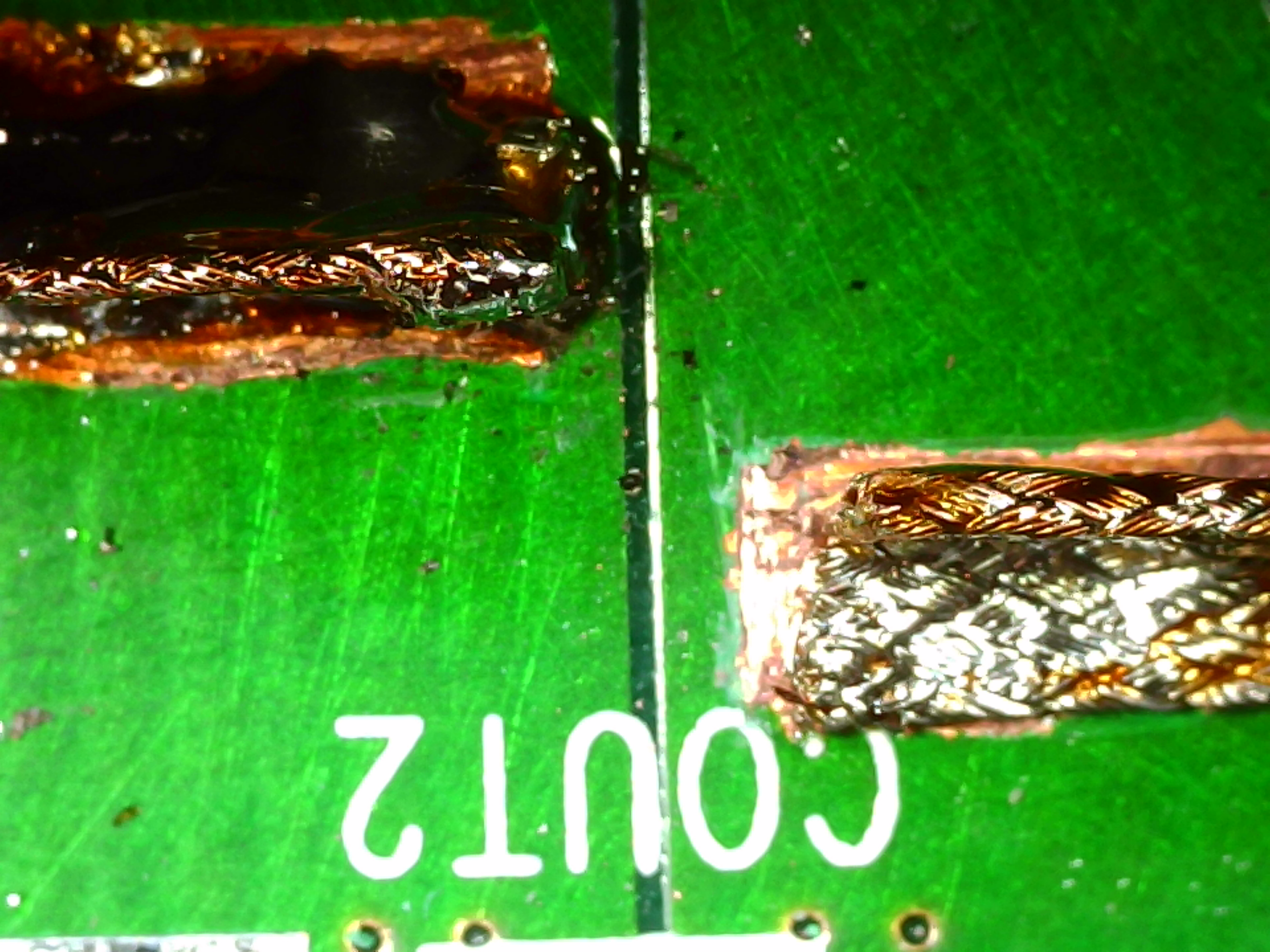
Solder in the LB3058A Current Source.
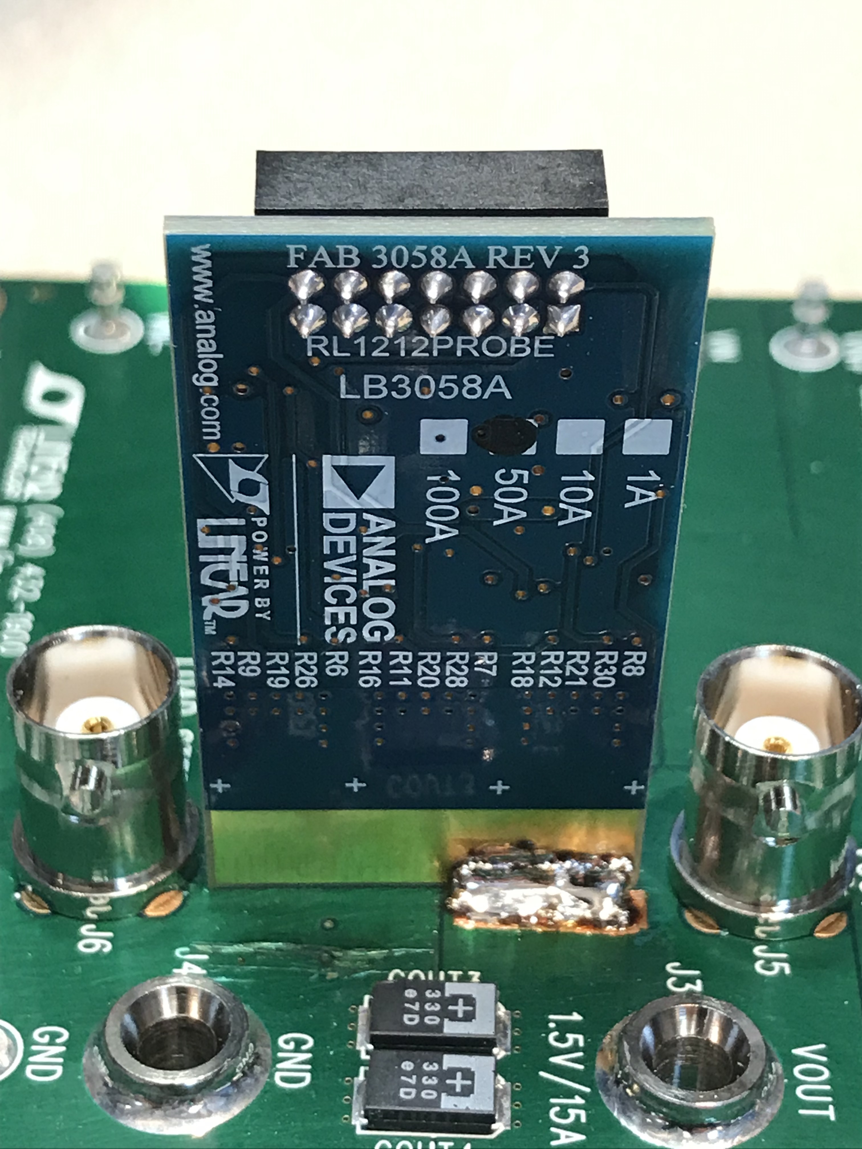
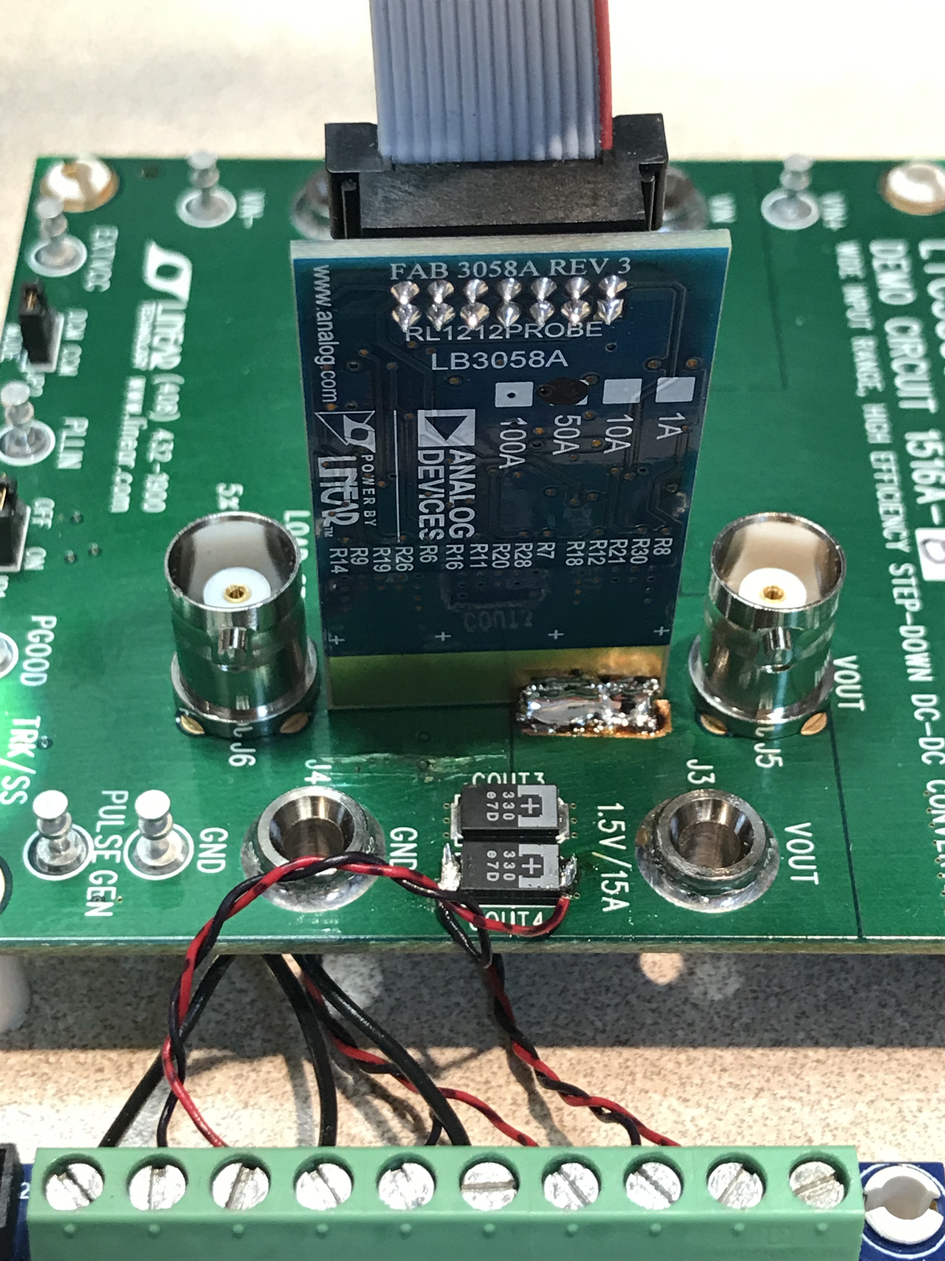
Connect the Vout+ and Vout- wires to the terminal block and plug in the 14-pin ribbon cable.
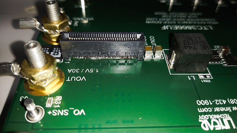
Method 3: Socket Installation Method
In this method, a 60-position female connector or edge rate card socket will be used for installing current probes to your DUT.
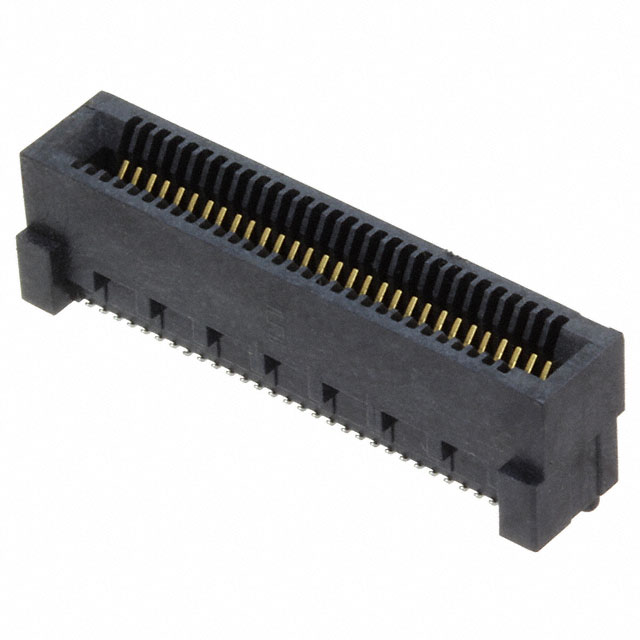
Figure 13 60-Position Female Connector or Edge Rate Card Socket
This method is similar to the soldering-braid method, requiring to scrape off the solder mask on the board. However, it provides more flexibility in installing and swapping out current probes.
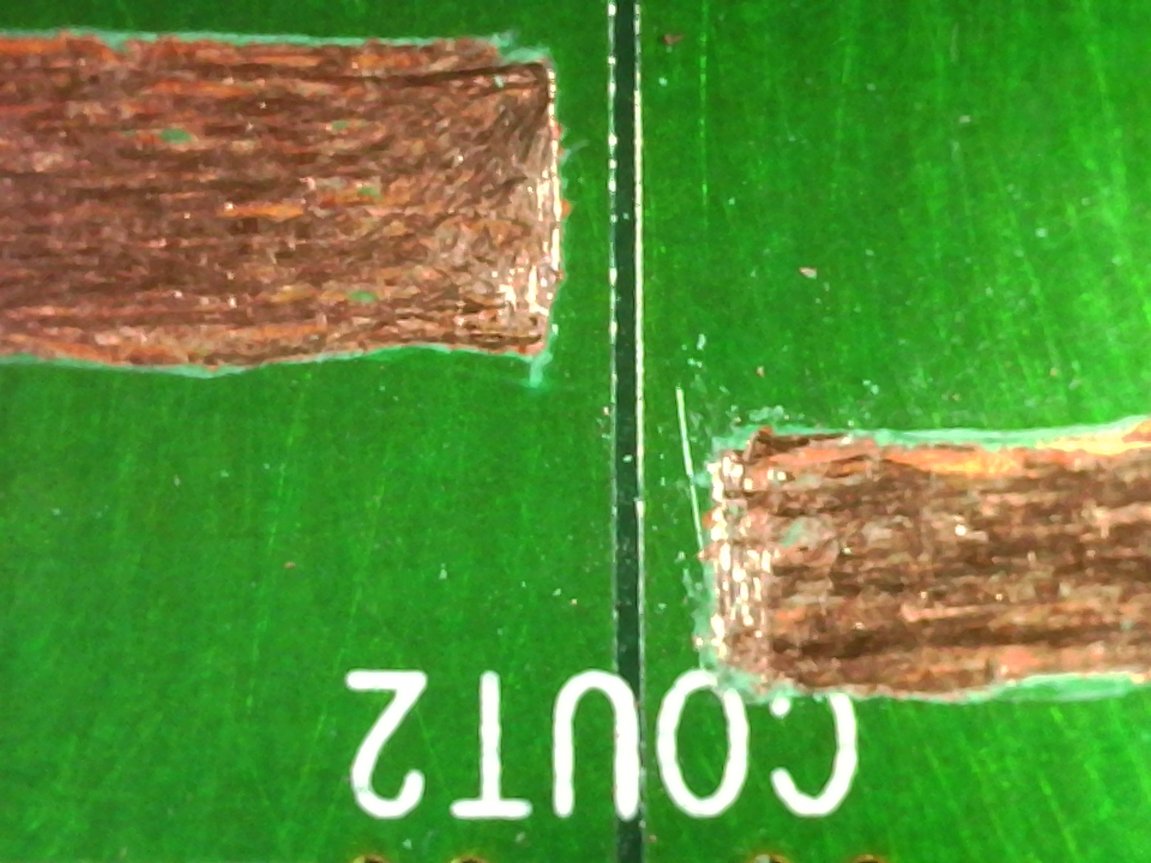
Scrape off the solder mask on the GND and Vout Planes to expose the copper for connection. Ensure that the scrapped regions will be able to accommodate the length and required soldering space for the female socket connector.
It is recommended to tin the exposed copper region for ease of soldering later.
Solder the female socket connector to the exposed copper.
Ensure proper connection via a continuity check. Check for possible shorts as well.
Tip
The LTpowerAnalyzer™ Kit comes with an easy-to-use graphical user interface, designed to be used in conjunction with the hardware components. To access the installer and learn how to use the built-in tools, visit the EVAL-LTPA-KIT Software User Guide page.
Resources
Help and Support
For questions and more information, please visit the Analog Devices EngineerZone.