EVAL-CN0581-EBZ
Configurable USB-C Power Sink Solution.
Overview
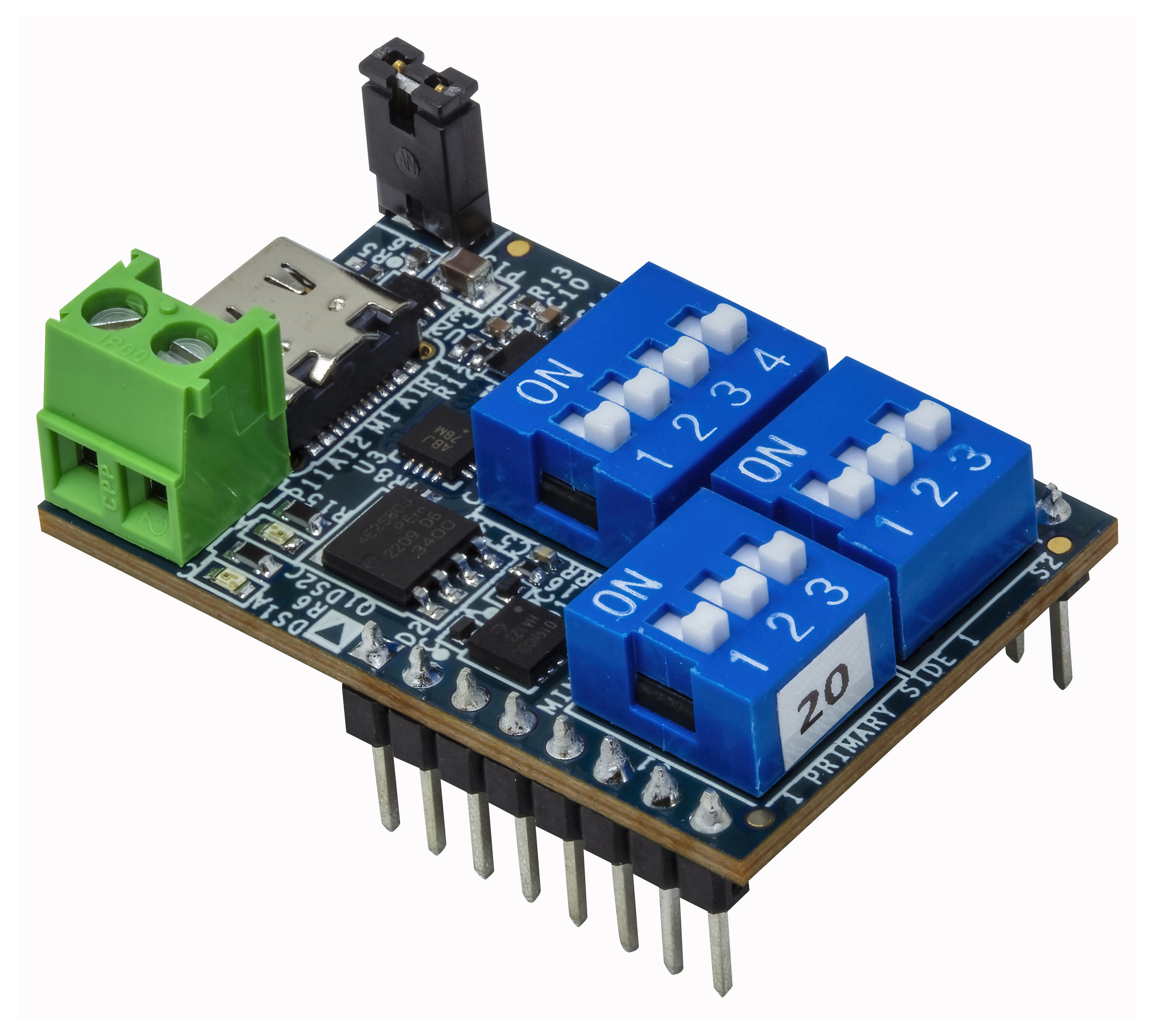
The EVAL-CN0581-EBZ is a standalone USB-C power delivery (PD) module that adds USB-C power sink capability to projects and devices, replacing traditional power jacks. Voltages of 5 V, 9V, 15 V, or 20 V at currents from 0.5 A to 5 A are supported, selected via dual in-line (DIP) switches. A hot-swap surge stopper with ideal diode allows charging of large bulk bypass capacitors, and an enable output enables the downstream load after ramp up is complete, while preventing reverse current during faults. No software control is required for operation; the preloaded firmware configuration reads the DIP switches and sets the power delivery object (PDO) voltage and current modes accordingly. Custom configurations can be optionally programmed via an I2C interface.
Features
USB Type-C power delivery standalone controller
Surge stopper with ideal diode which provides: - Overcurrent and short circuit protection - Input overvoltage protection - Input undervoltage protection - Output overvoltage protection - Reverse current protection - Robust power-up into large bulk capacitors up to 1000 µF - Enable output pin
On-board DIP switches allowing customization of VBUS voltage and current settings
Breadboard 2.54 mm pitch pin headers for easy prototyping
Applications
Smart speakers
Power tools
Wearables
Cameras
IoT devices
VR headset
Gaming consoles
Drones & robots
Hardware Configuration
Board Overview and Pinout Description
Below photos show the top view (left image) and bottom view (right image) of the EVAL-CN0581-EBZ and its main components:
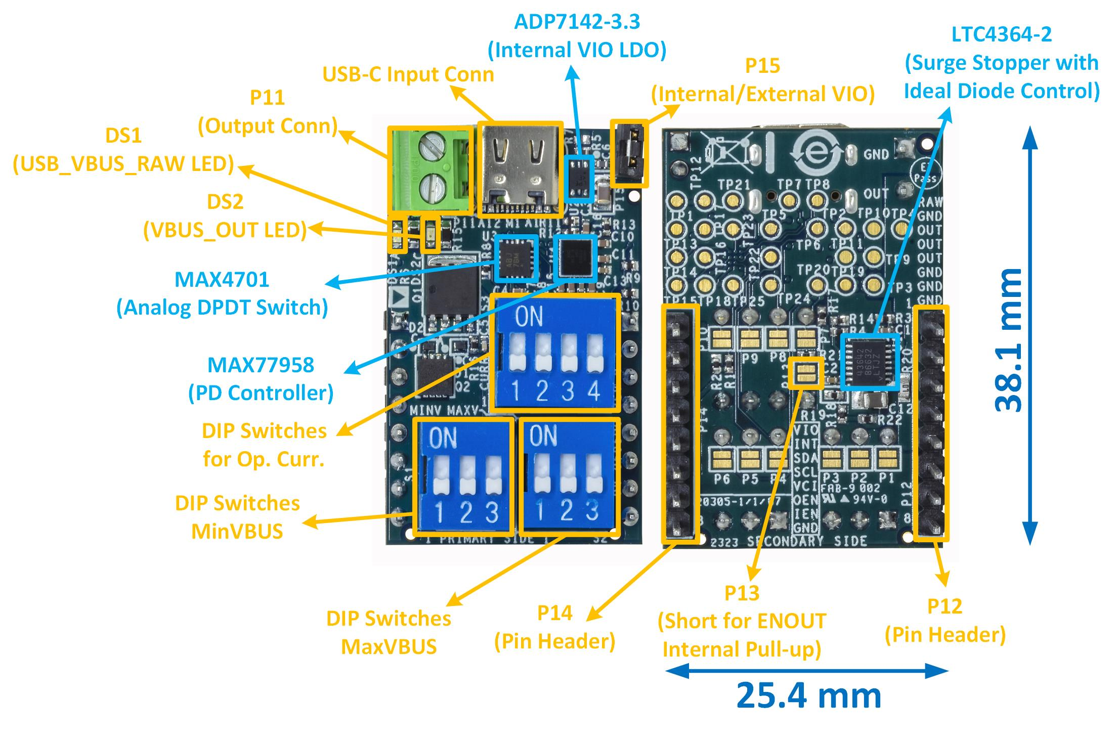
The EVAL-CN0581-EBZ pinout is described below:
Connectors and Pins |
Schematic Pin Name |
On-board Silkscreen Symbol |
Pin Description |
|---|---|---|---|
P12 Pin 1 |
USB_VBUS_RAW |
RAW |
Input VBUS |
P11 Pin 2; P12 Pins 3, 4, 5 |
VBUS_OUT |
OUT |
VBUS Output |
P14 Pin 1; P15 Pin 2 |
PPVIO |
VIO |
I/O Logic Voltage |
P14 Pin 2 |
USR_INT# |
INT |
Interrupt pin of MAX77958 PD Controller |
P14 Pin 3 |
USR_SDA |
SDA |
I2C Serial Data of MAX77958 PD Controller |
P14 Pin 4 |
USR_SCL |
SCL |
I2C Serial Clock of MAX77958 PD Controller |
P14 Pin 5 |
PRG_VCIN |
VCI |
MTP and |
P14 Pin 6 |
ENOUT |
OEN |
Open Drain Output Enable provided by LT4364-2 Surge Stopper |
P14 Pin 7 |
USR_OUT_EN |
IEN |
External Input Enable for LTC4364-2 Surge Stopper |
P11 Pin 1; P12 Pins 2, 6, 7, 8; Pin 14 Pin 4 |
GND |
GND |
Ground |
P15 Pin 1 |
PP3V3_LDO |
Internal 3V3 IO Voltage - place jumper on P15 to use internal 3V3 |
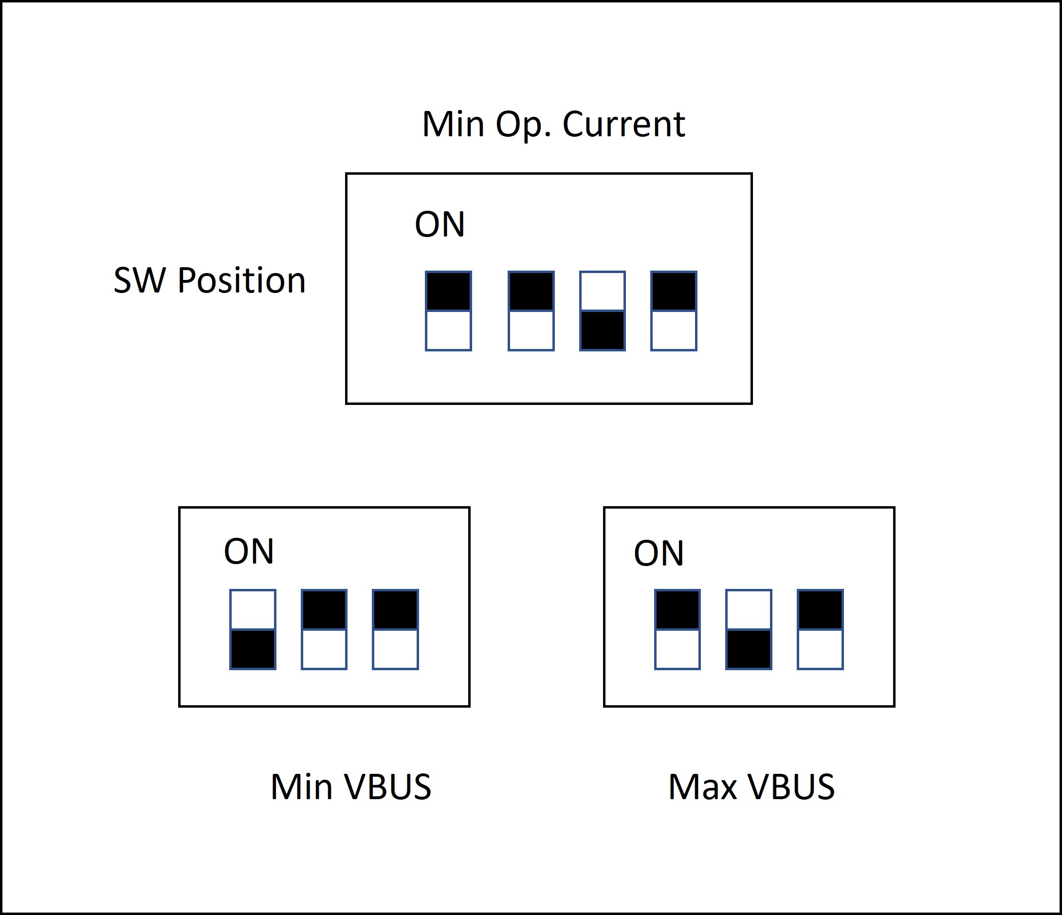
VBUS Voltage and Current Settings
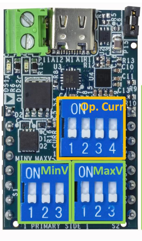
The EVAL-CN0581-EBZ board includes three dual in-line package (DIP) switches for the selection of the minimum VBUS voltage requested from the source, Min VBUS (“MINV” on silkscreen), the maximum VBUS voltage requested from the source, Max VBUS (“MAXV” on silkscreen), and the maximum current required from the source, Operating Current (“CURR” on silkscreen).
Below is a picture with the top side of EVAL-CN0581-EBZ, where Min VBUS, Max VBUS, and Operating Current DIP switches are highlighted:
The settings for VBUS Current and Voltage will take place only at power-up. Change these settings when the board is powered off or do one power cycle if the settings were changed when the board is powered on.
Here are two tables with all the combinations possible, one for the Operating Current DIP switch and one for Min/Max VBUS Voltage DIP switches:
Current Switch States |
Option |
|||
|---|---|---|---|---|
SW1 |
SW2 |
SW3 |
SW4 |
Operating Current |
OFF |
OFF |
OFF |
OFF |
0.5 A |
OFF |
OFF |
OFF |
ON |
1 A |
OFF |
OFF |
ON |
OFF |
1.5 A |
OFF |
OFF |
ON |
ON |
2 A |
OFF |
ON |
OFF |
OFF |
2.5 A |
OFF |
ON |
OFF |
ON |
3 A |
OFF |
ON |
ON |
OFF |
3.5 A |
OFF |
ON |
ON |
ON |
4 A |
ON |
OFF |
OFF |
OFF |
4.5 A |
ON |
OFF |
OFF |
ON |
5 A |
ON |
OFF |
ON |
OFF |
5 A |
ON |
OFF |
ON |
ON |
5 A |
ON |
ON |
OFF |
OFF |
5 A |
ON |
ON |
OFF |
ON |
5 A |
ON |
ON |
ON |
OFF |
5 A |
ON |
ON |
ON |
ON |
5 A |
Voltage Switch States |
Option |
||
|---|---|---|---|
SW 1 |
SW 2 |
SW3 |
Min/Max VBUS |
OFF |
OFF |
OFF |
5 V |
OFF |
OFF |
ON |
9 V |
OFF |
ON |
OFF |
12 V |
OFF |
ON |
ON |
15 V |
ON |
OFF |
OFF |
20 V |
ON |
OFF |
ON |
20 V |
ON |
ON |
OFF |
20 V |
ON |
ON |
ON |
20 V |
For the input power supply, any USB Type-C charger can be used. The fixed PDOs stated by PD 3.0 that can be selected by EVAL-CN0581-EBZ are:
5V at 3A
9V at 3A
12V at 3A
15V at 3A
20V at 5A
Note that not all power sources provide these exact combinations of voltages and currents. For example, a high-power laptop charger may provide 20 V at 6.5A (above the official USB-C standard), 5V at only 1A (below the standard), and no support for 9V or 12V, as compared to a general-purpose 45 W adapter which may provide 5V, 9V, 12V, and 15V at 3A (adheres to the USB-C standard) and 20 V at 2.25 A (below the standard).</note>
- To request a valid PDO, the following conditions must be satisfied by at least
one available PDO from the source:
Source PDO Voltage must be less or equal than Max VBUS setting
Source PDO Voltage must be higher or equal than Min VBUS setting
Source PDO Current must be higher or equal than Operating Current setting
If 2 or more PDOs meet all these three conditions, the PDO with the highest power (Voltage × Current) will be chosen.
If at least one of the above conditions is not satisfied, EVAL-CN0581-EBZ will function as described below depending on the chosen settings:
If Min VBUS > Max VBUS, VBUS_OUT (the output power pin of EVAL-CN0581-EBZ) defaults to 5V/3A requirements.
If Min VBUS < Max VBUS, the on-board surge stopper is kept closed and VBUS_OUT = 0 V (the output of the board is disconnected from the VBUS line).
I/O Logic Voltage Configuration (Jumper)
In order for the board to function, it needs an I/O logic supply voltage between 3.3 V and 5 V. The EVAL-CN0581-EBZ has an on-board ADP7142 low dropout regulator, which can be used by placing the one row and two pins jumper provided on P15. If another I/O logic supply voltage needs to be used (between 3.3 V and 5 V), it can be added on P14 -> Pin 1 or on P15 -> Pin 2 (do not place the jumper on P15 in this case).
LED Indicators
On the EVAL-CN0581-EBZ, there are two LEDs indicating the power at the input and the output. LED DS1 (if on) indicates that power at USB_VBUS_RAW (input) is present; and LED DS2 (if on) indicates that power at VBUS_OUT (output) is present. After powering the board, if a fault behavior is present or if the settings on the DIP switches are out of range, the surge stopper is kept closed and LED DS2 is turned off.
System Setup
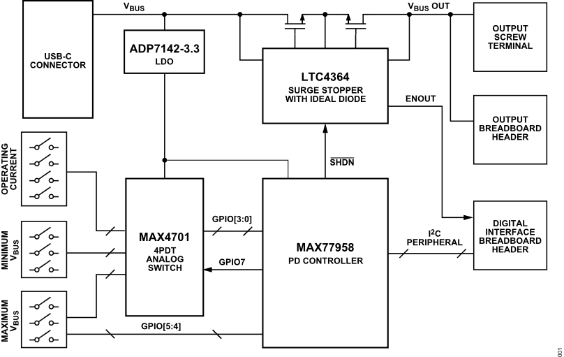
The EVAL-CN0581-EBZ can be easily tested using just a multimeter and a Type-C charger. A block diagram with a setup example is provided in the figure below. For this setup, check if cable supports powers wanted to be tested. To support all settings, make sure the cable is rated for 5 A, 20 V.
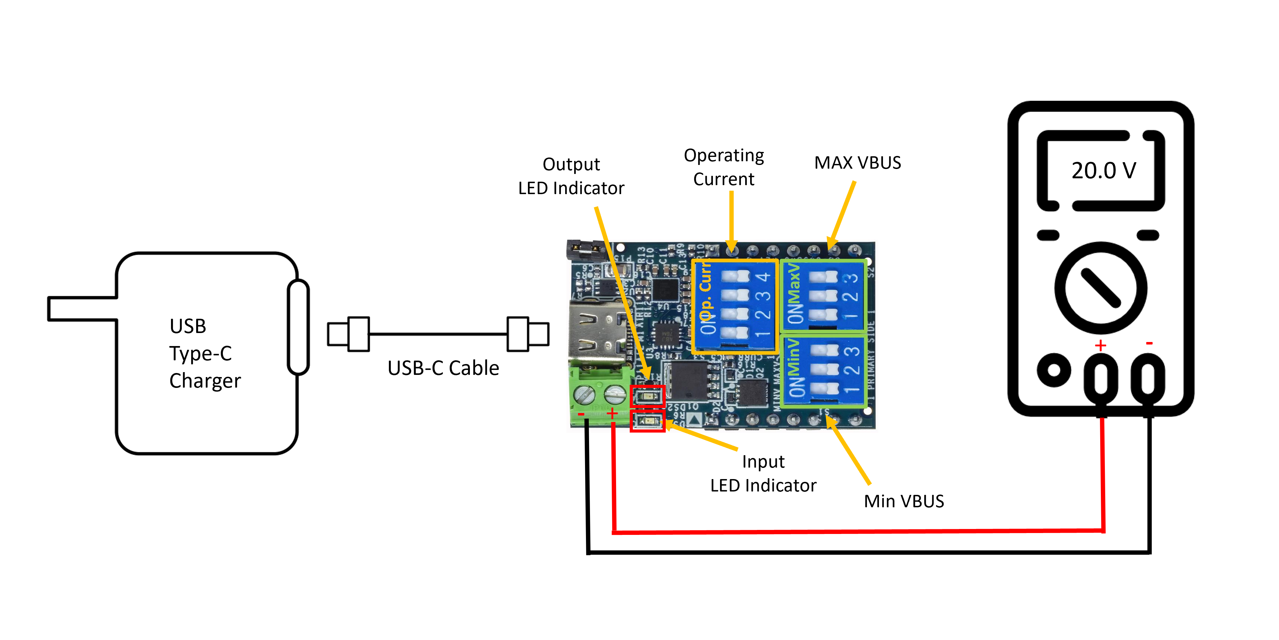
To evaluate the EVAL-CN0581-EBZ, use the internal 3.3 V logic voltage by placing a 2.54 mm pitch jumper with one row and two pins on P15 connector. If an external logic voltage is needed, it can be provided on PPVIO pin (between 3.3V and 5V).
Equipment Needed
EVAL-CN0581-EBZ circuit evaluation board
USB-C power charger (preferred with 100 W capability)
USB Type-C cable (rated for 20 V and 5 A)
Any device that accepts the available power
A voltmeter or multimeter
Getting Started
Choose the settings for the Min and Max VBUS and Operating Current and place the two-pin jumper provided on P15 connector for selecting the onboard 3.3V I/O logic voltage. Settings must be selected before the board is powered on.
Connect the EVAL-CN0581-EBZ output (P11 output connector or P14 pin header) to the device you want to power.
Connect the EVAL-CN0581-EBZ to a USB-C charger that can provide the Output Settings selected at 1.
Measure the output of EVAL-CN0581-EBZ with the voltmeter/multimeter between VBUS_OUT and GND (see pinout description).
Examples of Different Voltage and Current Settings
To obtain the desired set power, the first step is to select a USB-C charger that can provide the desired PDO. In the table below are shown the fixed PDOs of a 96W USB-C power charger.
Power Delivery Object (PDO) |
||
|---|---|---|
Voltage (V) |
Current (A) |
Power (W) |
5.2 |
3 |
15.6 |
9 |
3 |
27 |
15 |
3 |
45 |
20.5 |
4.7 |
96.35 |
The following examples consist of different settings of Min VBUS, Max VBUS, and Operating Current, using the EVAL-CN0581-EBZ and the power adapter with the PDOs described in the table above.
Example 1
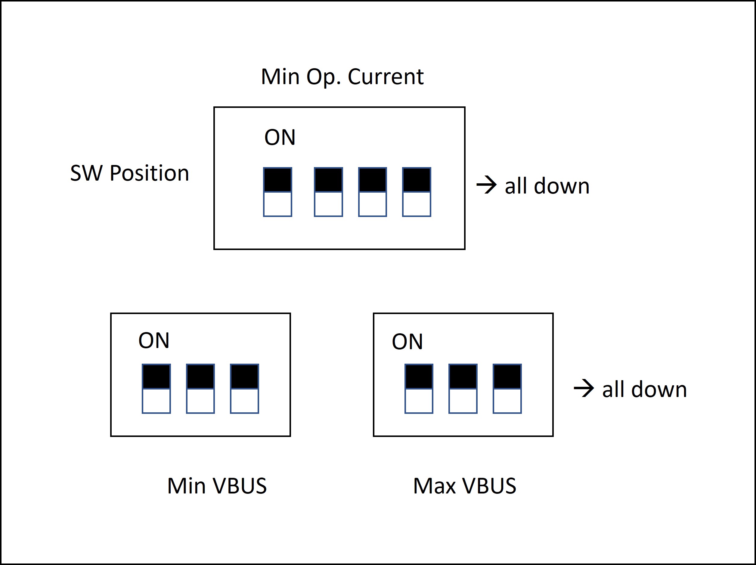
Settings:
Operating Current = OFF | OFF | OFF | OFF —> 0.5A
Min VBUS = OFF | OFF | OFF —> 5V
Max VBUS = OFF | OFF | OFF —> 5V
After powering on EVAL-CN0581-EBZ:
Surge Stopper : ON
Input DS1 LED : ON (Input voltage present)
Output DS2 LED : ON (Output voltage present)
Measured Output Voltage: 5.2V
In this example, EVAL-CN0581-EBZ selects 5.2V/3A because the 96 W charger has 5.2V available (falls in the 5V fixed supply output range [PDO Voltage * 0.95; PDO Voltage * 1.05]) and the operating current requested (0.5A) is less than the maximum value provided by the charger at 5.2V (0.5A < 3A).
Example 2
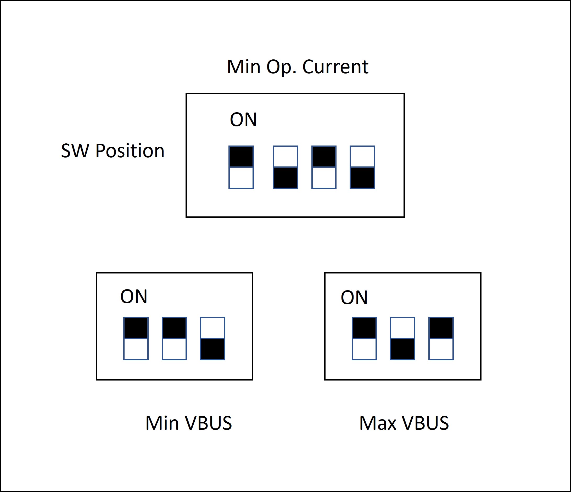
Settings:
Operating Current = OFF | ON | OFF | ON —> 3A
Min VBUS = OFF | OFF | ON —> 9V
Max VBUS = OFF | ON | OFF —> 12V
After powering on EVAL-CN0581-EBZ:
Surge Stopper : ON
Input DS1 LED : ON (Input voltage present)
Output DS2 LED : ON (Output voltage present)
Measured Output Voltage: 9V
Here EVAL-CN0581-EBZ selects 9V/3A because this is the maximum output power that the charger can provide between 9V and 12V. Also, the operating current requested can be provided by the charger (3A).
Example 3
Settings:
Operating Current = OFF | ON | ON | OFF —> 3.5A
Min VBUS = OFF | ON | ON —> 15V
Max VBUS = OFF | ON | ON —> 15V
After powering on EVAL-CN0581-EBZ:
Surge Stopper : OFF
Input DS1 LED : ON (Input voltage present)
Output DS2 LED : OFF (Output voltage absent, = 0V)
Measured Output Voltage: 0V
With these settings, EVAL-CN0581-EBZ keeps the surge stopper closed and the output is 0 V because the operating current requested (3.5A) is greater than what the charger can provide at 15A (3A).
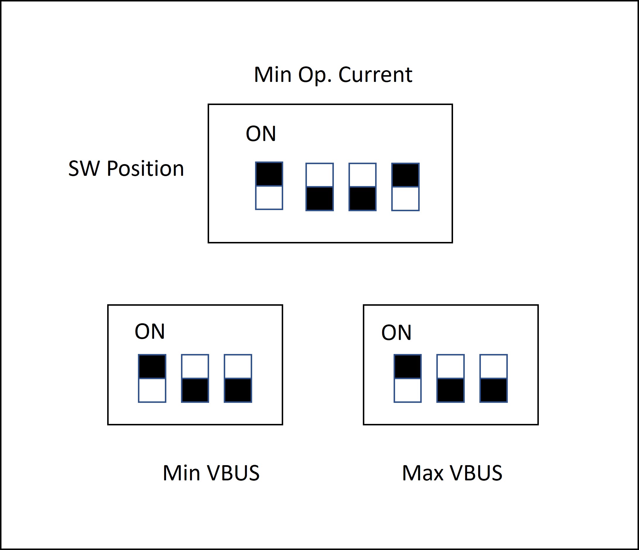
Example 4
Settings:
Operating Current = OFF | OFF | ON | OFF —> 1.5A
Min VBUS = ON | OFF | OFF —> 20V
Max VBUS = OFF | ON | OFF —> 12V
After powering on EVAL-CN0581-EBZ:
Surge Stopper : ON
Input DS1 LED : ON (Input voltage present)
Output DS2 LED : ON (Output voltage present)
Measured Output Voltage: 5.2V
EVAL-CN0581-EBZ defaults to 5V/3A PDO because the selected Min VBUS (20V) is greater than Max VBUS (12V).
More information and useful links
Design and Integration Files
Download
EVAL-CN0581-EBZ Design & Integration Files
Schematics
PCB Layout
Bill of Materials
Allegro Project
LTspice Simulation File
Help and Support
For questions and more information about this product, connect with us through the Analog Devices EngineerZone.