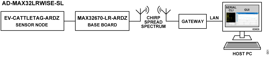
AD-MAX32LRWISE-SL
Long Range Wireless Radio Development Kit based on MAX32670 MCU and LR1110 RF Transceiver.
Overview
The AD-MAX32LRWISE-SL development kit is a tool intended for designing solutions based on low-power, long range proprietary radio communication technique. This platform features the LR1110, an RF transceiver based on spread spectrum modulation techniques derived from chirp spread spectrum (CSS) technology, and supports a frequency range from 800 MHz to 960 MHz. This solution is also based on the MAX32670 ultralow power microcontroller based on ARM Cortex-M4 processor.
The kit is composed of a development board and equipped with sensor modules, providing users with a complete system that is suitable for quick prototyping and development of IoT applications. The design includes a gateway, which is crucial for establishing connectivity between the LPWAN devices and the backend or application server. This component is vital for data transfer and communication.
This also comes with software that allows users to observe nodes in a graphical user interface (GUI) dashboard. This feature enhances the monitoring and management capabilities of the system. To use the development board, users need to flash it with functional firmware. A simple join example has been open-sourced, providing more flexibility and easy customization in terms of firmware development.
Overall, the AD-MAX32LRWISE-SL development kit offers a comprehensive and user-friendly solution for individuals or developers interested in exploring and implementing LPWAN technology for IoT applications.
Features
Provides the user with a platform to evaluate the features and performance of the evaluation kit.
Allows the user to prototype and test their IoT applications before moving on to full-scale development.
Provides tools for analyzing the power consumption of the device, helping the user to optimize their applications for energy efficiency.
Includes development tools, libraries, and documentation to assist user in writing and debugging their code.
Helps the user analyze and study the different modulation schemes, data rates, and other parameters relevant to IoT communication.
Comes with user-friendly interfaces, documentation, and software tools that simplify the integration process which can save developers time and effort when incorporating the LR1110 into their IoT devices.
Applications
Battery-Powered Medical Devices
Industrial Sensors
Optical Communication Modules
Secure Radio Modem Controller
Smart Sensor Controller
System Housekeeping Controller
What’s Inside the Box
System Architecture
Specifications
MCU |
|---|
Arm Cortex-M4 Core with FPU up to 100 MHz |
384 kB flash memory with error correction |
160 kB SRAM (128 kB with ECC enabled), optionally preserved in lowest power modes |
Security |
Available secure boot |
Support cryptographic algorithms, including AES-128/192/256, 1024-bit DSA, 2048-bit (CRT) and secure boot loader |
Power |
Ultralow Power Real Time Clock (RTC) with Integrated Power Switch |
With 300 nA power consumption during sleep mode |
Long Range Radio |
Support FSK, GFSK, MSK, GMSK, and Long Range FHSS modulations |
Programmable bit rate up to 62.5 kbps and 300 kbps |
Support of all major sub-GHz ISM bands from 800 MHz to 960 MHz |
High sensitivity: down to -148 dBm |
Low power multi-constellation GNSS scanner/ passive Wi-Fi AP MAC address scanner (only available for LR1110 radio chip) |
Components
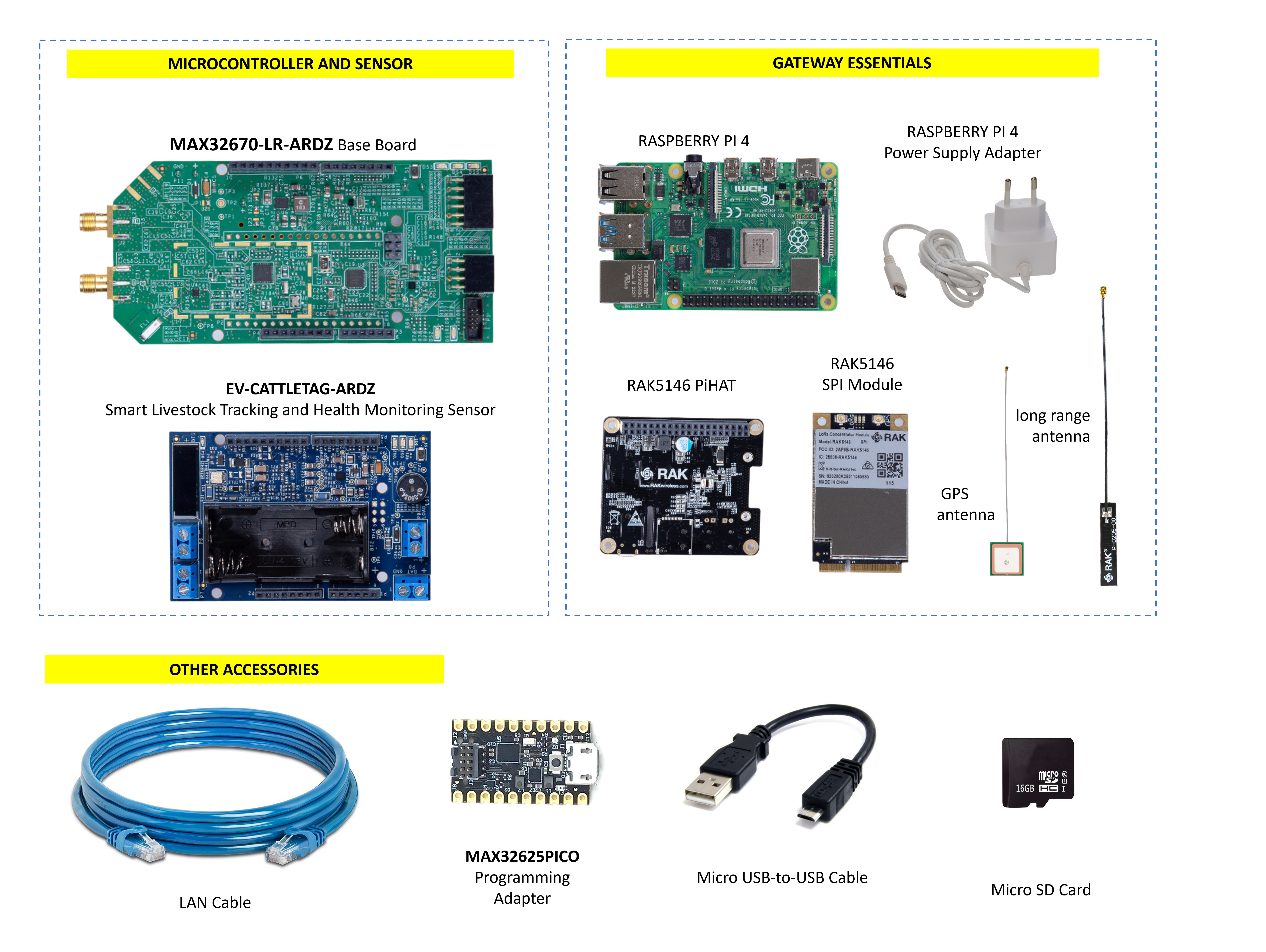
When you purchase the AD-MAX32LRWISE-SL development kit, the package comes with the following boards and accessories:
Base Board
MAX32670-LR-ARDZ Baseboard
Component Sensor Node
EV-CATTLETAG-ARDZ Sensor for Livestock Tracking and Health Monitoring
Gateway Concentrator
RAK5146 PiHAT Kit
Raspberry Pi 4 Model B with Power Supply Adapter
MAX32625PICO Programming Adapter
Micro SD Card
LAN Cable
What is a Base Board?
A Base Board contains an RF transceiver chip and a microcontroller, which combine all the required elements for long range communication. This platform uses the chirp spread spectrum technique, allowing sensors to connect to a network and send and receive data in long distances.
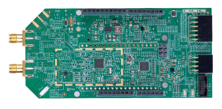
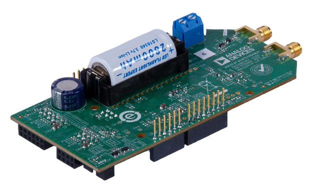
MAX32670-LR-ARDZ Base Board
The MAX32670-LR-ARDZ Base board consists of the MAX32670 high-reliability, ultralow power microcontroller based on Arm Cortex-M4 processor, and the LR1110 long range RF transceiver module.
What are Sensor Nodes?
Sensor nodes are devices that send or receive messages through wireless communication to and back from the gateways. These devices communicate with nearby gateways connected through a network server. Depending on the intended applications, sensors can transmit various type of data such as temperature, flow rate, vibration, etc.
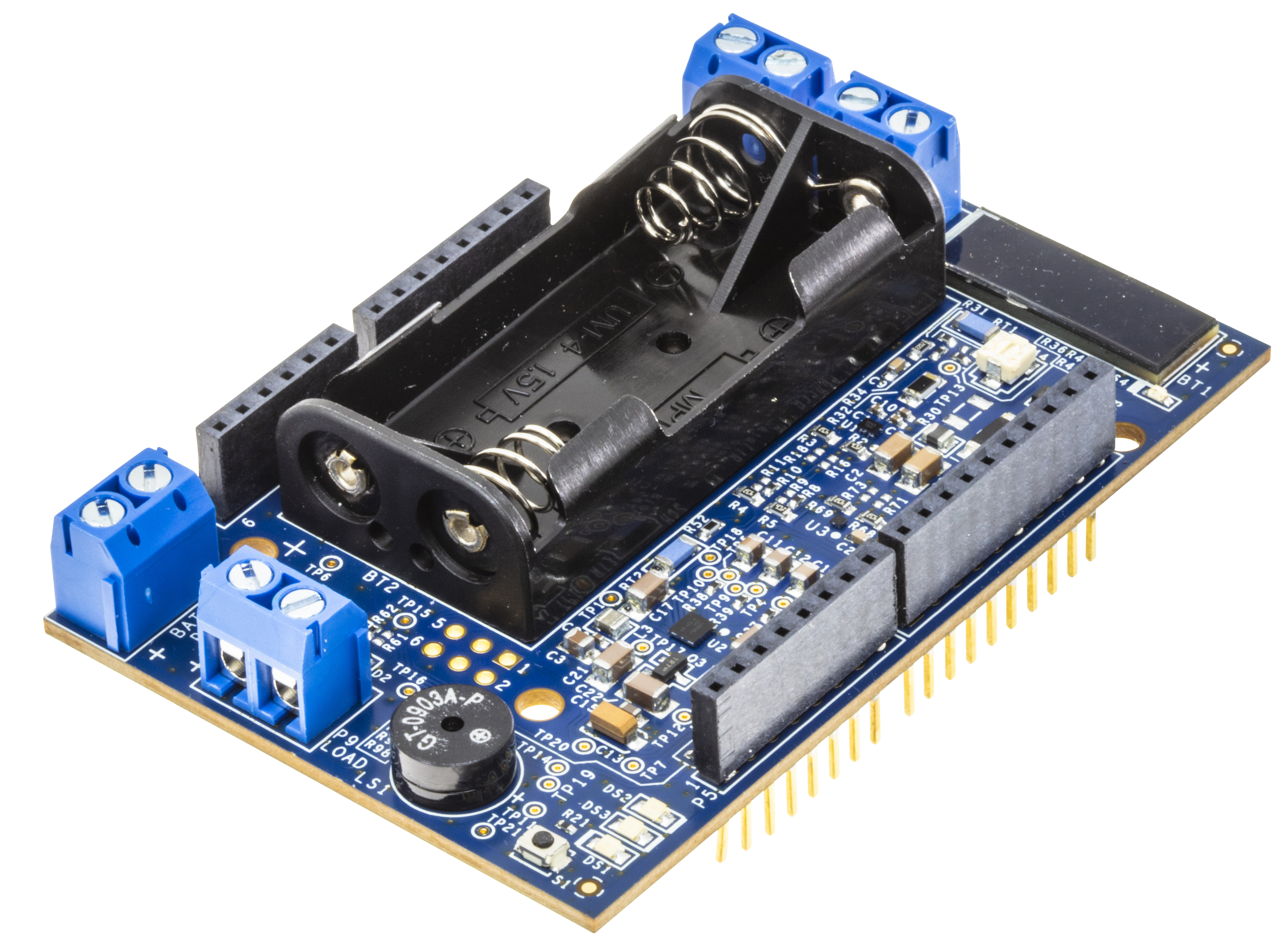
EV-CATTLETAG-ARDZ Sensor for Livestock Monitoring
The EV-CATTLETAG-ARDZ is a system module that uses ADI power solution on the controller and transceiver module used for virtual fencing solution for livestock, where the animals are controlled by GPS-collars and an app. The system is consisting of a MAX20361 power harvester, MAX20335 BMS, and a MAX30210 temperature sensor and a buzzer with an option for vibration motor.
System Setup
Hardware Setup
Note that this setup only applies for MAX32670-LR-ARDZ Base Board. Users may use a different base board or microcontroller, however the firmware built for this demo application cannot be used as this is specifically designed for the MAX32670-LR-ARDZ.
Equipment Needed
One (1) MAX32670-LR-ARDZ Base Board
One (1) EV-CATTLETAG-ARDZ Sensor Node
One (1) MAX32625PICO Rapid Development Platform with 10-pin ribbon cable with firmware image
One (1) CR123A Battery or any equivalent external DC power supply (+3V to +4.7V). Note that this is not included in the kit
One (1) Micro USB to USB cable
Host PC (Windows 10 or later)
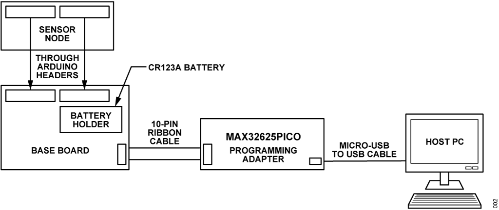
Insert one CR123A battery (3V to 4.7V) into the battery holder (BT1 connector) of the MAX32670-LR-ARDZ Base Board.
Tip
Make sure to check for the battery polarity in the BT1 connector, refer to the figure below. The DS3 LED will light up indicating that you have inserted the battery correctly and that power is provided in the base board.
Connect the EV-CATTLETAG-ARDZ to the MAX32670-LR-ARDZ Base Board by aligning the corresponding Arduino headers on each board.
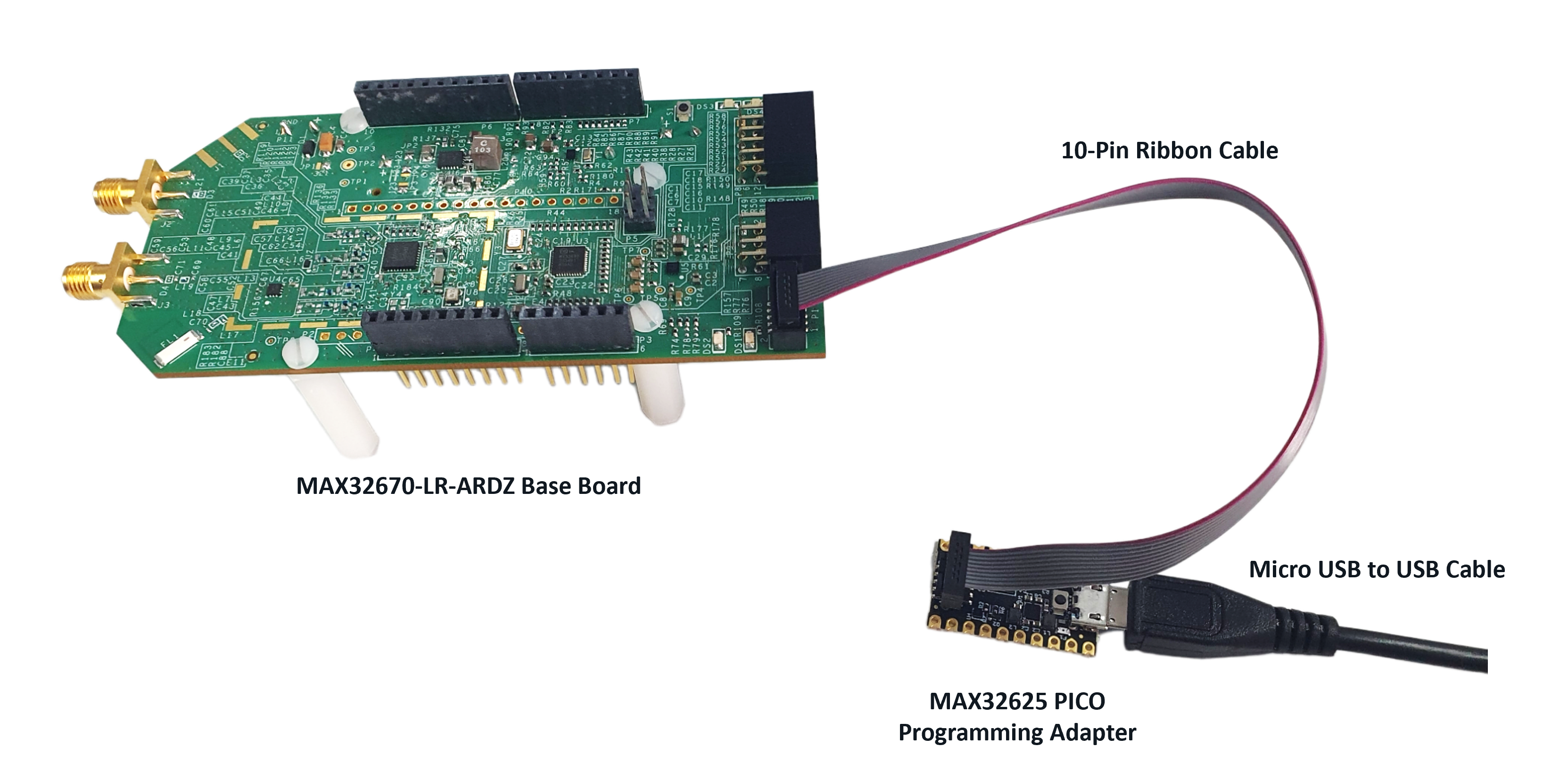
Connect the MAX32625PICO :adi:`MAX32625PICO programming adapter to the MAX32670-LR-ARDZ Base Board through the 10-pin ribbon cable.
Tip
Make sure that the MAX32625PICO programming adapter has been flashed with the correct image before connecting it to the MAX32670-LR-ARDZ Base Board.
How to flash the firmware image in the MAX32625PICO
Download the firmware image: MAX32625PICO Firmware Image for MAX32670
Do not connect the MAX32625PICO to the MAX32670-LR-ARDZ Base Board yet.
Connect the MAX32625PICO to the Host PC using the micro USB to USB cable.
Press the button on the MAX32625PICO. (Do not release the button until the MAINTENANCE drive is mounted).
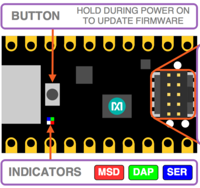
Release the button once the MAINTENANCE drive is mounted.
Drag and drop (to the MAINTENANCE drive) the firmware image.
After a few seconds, the MAINTENANCE drive will disappear and be replaced by a drive named DAPLINK. This indicates that the process is complete, and the MAX32625PICO can now be used to flash the firmware of the MAX32670-LR-ARDZ Base Board.
Connect the MAX32625PICO programming adapter to the Host PC using the micro USB to USB cable.
Once you have completed this setup, proceed to PHASE 2 found in ADI Long Range Wireless Radio Software User Guide.
Resources
FAQs
Q. Why is the serial application not responding after opening the port?
A. It usually happens whenever the power of the base board is not enough to operate the board.
Q. Can we use other gateways aside from ChirpStack?
- A. Customers are not limited to use ChirpStack gateway, it is possible to use
other gateways available in the market.
Q. What maximum number a gateway can handle?
- A. It depends on the channels available per assigned region and the time
division set by the user on sending data from the nodes to gateway.
Q. Is there another way to see the GUI without using the local setup?
A. The GUI can also be accessed through cloud service, but it is not supported by ADI.
Q. What is the maximum distance the gateway and nodes can communicate?
- A. The gateway and nodes’ maximum and effective range may vary depending on
the modulation parameters, transmit power, antenna gain, environmental conditions, and obstacles present in the communication path. In practice, it can reach several kilometers in rural areas with a clear line of sight. The effective range may be shorter in urban areas where obstacle and interference are present.
Help and Support
For questions and more information about this product, connect with us through the Analog Devices Engineer Zone.