Software User Guide
Evaluation
The evaluation kit comes with the MAX32650 preprogrammed with a firmware that is ready to use as-is. If you’ve gone through the hardware setup and you’ve connected at least the power and the Ethernet cables to the two boards of the setup, the firmware takes care of establishing and maintaining a wireless link automatically on power on.
Software Setup
Wethlink GUI is an optional software that can be used to configure the
firmware operation from a PC. The firmware establishes a wireless link
automatically without any input from the Wethlink GUI. For a quick evaluation of
the ADMV96S-WGBE-EK1 you need not use the software at all. But if you want to
better observe or change the behavior of the firmware or want access to the raw
registers of the devices, you may use the software to achieve that, and this
page walks you through the installation process..
Requirements
Windows
Linux
git
python3
pip
Installing the Wethlink GUI on Windows
To install the GUI double click the
wethlink_installer.exefile. When prompted pressInstalland after the setup is completed pressClose.
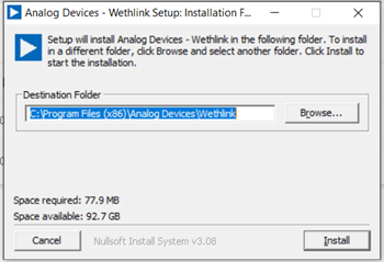
After installation the app is found at the path of the Destination Folder in the previous step.
You can start the app by double clicking the
wethlink.exefile in the destination folder or by launching it from the Windows start menu.
Running the Wethlink GUI on Linux
There is no installer provided on Linux, you have to clone the repo, install the dependencies and run the app in python.
~$
git clone https://github.com/analogdevicesinc/wethlink.git # TODO: does not exist yet
~$
cd wethlink
~/wethlink$
pip install PyQt6 pyserial pylibiio
~/wethlink$
python wethlink.py
Firmware Installation
How to find the firmware version?
Boot message
When a board is powered up or reset with the RESET button, the firmware starts executing and prints some messages over the serial port. You may access the serial port by connecting a MAXDAP to the JTAG SWD header and to the PC. To view the boot messages, open up a serial terminal application of your choice and configure it to listen to the serial port that appears in your system when you connect the MAXDAP to the PC (COMx on Windows, /dev/ttyACMx on Linux). The serial port settings must be 115200 baud, 8 databits, no parity bits, 1 stopbit, no flow control signals.
A typical boot message looks like this:
tags/wethlink-v1.0.0-7c98c2261 for revision B
Transceiver: admv9625
EEPROM: loading non-volatile parameters...
EEPROM: loaded non-volatile parameters.
Running IIOD server...
If successful, you may connect an IIO client application by:
1. Disconnecting the serial terminal you use to view this message.
2. Connecting the IIO client application using the serial backend configured as shown:
    Baudrate: 345600
    Data size: 8 bits
    Parity: none
    Stop bits: 1
    Flow control: none
The firmware version is thus v1.0.0, built using git commit 7c98c2261
for revision B hardware.
Using libiio from command line
The libiio (v0.25 or later) library setup also installs some useful command
line tools such as iio_info which can connect to a remote iiod
applciation and display information about it. In our case, the firmware is
running an iiod application, as can be seen in the boot message, so we can
query it over the serial port (replace /dev/ttyACM0 with COMn on Windows):
~$
iio_info -u serial:/dev/ttyACM0,345600,8n1n
iio_info version: 0.25 (git tag:v0.25)
Libiio version: 0.25 (git tag: v0.25) backends: local xml ip usb serial
IIO context created with serial backend.
Backend version: 1.1 (git tag: 0000000)
Backend description string: no-OS/projects/wethlink tags/wethlink-v1.0.0-7c98c2261
[...]
We can conclude that the on-board firmware is v1.0.0 built using git commit
7c98c2261.
Using Wethlink GUI
Simply connect to the serial port of the device with the Wethlink GUI app and observe the Context tab content.
How to update the firmware ?
Drag and drop a .hex
To update to a newer firmware version (such as the latest release), download the .hex file onto the DAPLINK drive that is created when you plug in the programmer. While the file is being copied, you will see the MAXDAP device blinking. Once the programming is done, the device reconnects again to the PC as a DAPLINK drive. Check this newly attached DAPLINK drive for a FAIL.TXT file. If it doesn’t exist, you have correctly programmed the board as in the following video:
If however, there is a FAIL.TXT file, if might be that the programmer isn’t connected correctly or that the firmware of the programmer itself is not a firmware that can program a MAX32650 target. Here’s how a failed programming looks like:
Is the MAXDAP firmware correct?
The MAXDAP itself needs to run a specific firmware version to be able to program the MAX32650 with Drag and Drop. The DETAILS.TXT file on the DAPLINK drive specifies the Git SHA of the running firmware:
Git SHA: 649f2a1524190c5f0ea32c97bb8682ad6fd772a0
If what you see on your device is not the one indicated above, please follow the instructions on this page to update the MAXDAP firmware first.
mcufla.sh
ADI no-OS repository provides a standalone script that can be used to program .elf files to various targets, including the MAX32650. Typical usage and output is shown below:
~$
wget https://raw.githubusercontent.com/analogdevicesinc/no-OS/master/tools/scripts/mcufla.sh
~$
chmod +x ./mcufla.sh
~$
./mcufla.sh ~/Work/no-OS/projects/wethlink/build/wethlink.elf
Maxim platform detected
Running cmd:
  /home/dari/.mcuflash/maxim/openocd/src/openocd
    -s /home/dari/.mcuflash/maxim/openocd/tcl
    -c 'adapter driver cmsis-dap; transport select swd; '
    -f target/max32650.cfg
    -c 'program /home/dari/Work/no-OS/projects/wethlink/build/wethlink.elf verify reset exit'
Open On-Chip Debugger 0.11.0+dev-g56a818e4c (2023-10-24-15:55)
Licensed under GNU GPL v2
For bug reports, read
    http://openocd.org/doc/doxygen/bugs.html
swd
Info : CMSIS-DAP: SWD  supported
Info : CMSIS-DAP: Atomic commands supported
Info : CMSIS-DAP: Test domain timer supported
Info : CMSIS-DAP: FW Version = 2.1.0
Info : CMSIS-DAP: Serial# = 042517028fbd037a00000000000000000000000097969906
Info : CMSIS-DAP: Interface Initialised (SWD)
Info : SWCLK/TCK = 1 SWDIO/TMS = 1 TDI = 0 TDO = 0 nTRST = 0 nRESET = 1
Info : CMSIS-DAP: Interface ready
Info : clock speed 2000 kHz
Info : SWD DPIDR 0x2ba01477
Info : max32xxx.cpu: Cortex-M4 r0p1 processor detected
Info : max32xxx.cpu: target has 6 breakpoints, 4 watchpoints
Info : max32xxx.cpu: external reset detected
Info : starting gdb server for max32xxx.cpu on 3333
Info : Listening on port 3333 for gdb connections
target halted due to debug-request, current mode: Thread
xPSR: 0x01000000 pc: 0x00000184 msp: 0x2000b300
** Programming Started **
** Programming Finished **
** Verify Started **
** Verified OK **
** Resetting Target **
shutdown command invoked
make run
This method involves installing the toolchain for building the
projects/wethlink project and uploading the generated binary to the target
with make run.
Hardware revision must be specified when building the wethlink project,
otherwise the build errors out. make HW_VERSION=0 builds for rev A hardware,
and make HW_VERSION=1 builds for rev B hardware.
Note
For instructions on how to build the project, please refer to the No-OS Build Guide
Theory of Operation
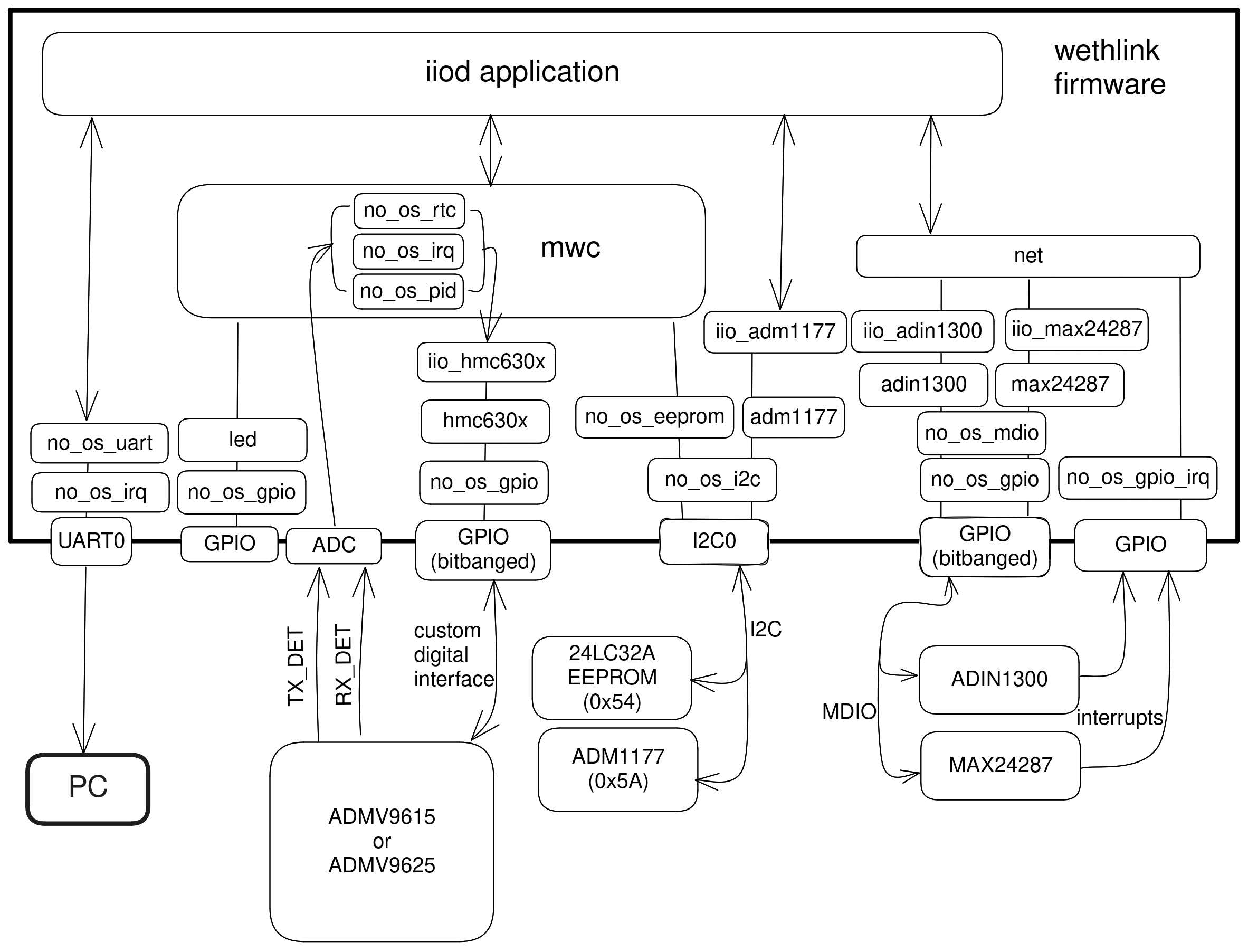
The firmware uses many no-OS modules for accessing the various peripherals it
needs for this project. The diagram below shows how these modules interact with
the hardware and with each other. Of particular interest is the feedback loop
from the embedded ADC that is periodically used to sample TX_DET and RX_DET at 1
Hz (provided by the embedded RTC) to the no_os_pid P.I.D. controller which
computes a new set of gain values that are written back into the transceiver.
This feedback loop is the core functionality of this system and it ensures that
the wireless link operates with optimum gains at any distance that the ADMV9615
and ADMV9625 are set apart.
A detailed view of this feedback loop is represented below, showing exactly what gains the feedback loop controls:

The firmware can also interact with a PC application over the serial line
(UART). Upon boot, it prints boot messages at 115200 baudrate, then launches an
iiod application that can be accessed from a PC using libiio over a
serial backend at 345600 baudrate. The following existing PC applications may be
used to interact with the firmware:
iio_info,iio_attr(command-line tools from Libiio )Wethlink GUI (Windows only)
The fact that the firmware exposes the on-board devices as iio devices in a standardized way means that it is easy to devise new applications that can interact with the firmware by simply using the Libiio library.
IIO devices
You can see all the iio devices and their channels and attributes below, as
obtained with iio_info:
~$
iio_info -u serial:/dev/ttyACM0,345600,8n1n
iio_info version: 0.25 (git tag:v0.25)
Libiio version: 0.25 (git tag: v0.25) backends: local xml ip usb serial
IIO context created with serial backend.
Backend version: 1.1 (git tag: 0000000)
Backend description string: no-OS/projects/wethlink tags/wethlink-v1.0.0-rc1-7c98c2261
IIO context has 9 attributes:
    hw_model: admv9625
    hw_version: b
    hw_serial: serial
    carrier_model: model
    carrier_version: b
    carrier_serial: serial
    uri: serial:/dev/ttyACM0,345600,8n1n
    serial,port: /dev/ttyACM0
    serial,description: DAPLink CMSIS-DAP - 042517028fbd037a00000000000000000000000097969906
IIO context has 6 devices:
    iio:device0: hmc6300
        1 channels found:
            temp:  (input)
            1 channel-specific attributes found:
                attr  0: raw value: 15
        8 device-specific attributes found:
                attr  0: enabled value: 1
                attr  1: vco value: 59850000
                attr  2: vco_available value: 55125000 55387500 55650000 55912500 56175000 56437500 56700000 56962500 57225000 57487500 57750000 58012500 58275000 58537500 58800000 59062500 59325000 59587500 59850000 60112500 60375000 60637500 60900000 61162500 61425000 61687500 61950000 62212500 62475000 62737500 63000000 63262500 63525000 63787500 64050000 64312500 64575000 64837500 65100000 65362500 65625000 65887500 66150000
                attr  3: vco_band value: 8
                attr  4: vco_lock value: 1
                attr  5: if_attn value: 15
                attr  6: temp_en value: 1
                attr  7: rf_attn value: 9
        1 debug attributes found:
                debug attr  0: direct_reg_access value: 0
        No trigger on this device
    iio:device1: hmc6301
        1 channels found:
            temp:  (input)
            1 channel-specific attributes found:
                attr  0: raw value: 15
        14 device-specific attributes found:
                attr  0: enabled value: 1
                attr  1: vco value: 63262500
                attr  2: vco_available value: 55125000 55387500 55650000 55912500 56175000 56437500 56700000 56962500 57225000 57487500 57750000 58012500 58275000 58537500 58800000 59062500 59325000 59587500 59850000 60112500 60375000 60637500 60900000 61162500 61425000 61687500 61950000 62212500 62475000 62737500 63000000 63262500 63525000 63787500 64050000 64312500 64575000 64837500 65100000 65362500 65625000 65887500 66150000
                attr  3: vco_band value: 15
                attr  4: vco_lock value: 1
                attr  5: if_attn value: 6
                attr  6: temp_en value: 1
                attr  7: rf_lna_gain value: 1
                attr  8: bb_attn1 value: 0
                attr  9: bb_attn2 value: 0
                attr 10: bb_attni_fine value: 0
                attr 11: bb_attnq_fine value: 0
                attr 12: bb_lpc value: 0
                attr 13: bb_hpc value: 0
        1 debug attributes found:
                debug attr  0: direct_reg_access value: 0
        No trigger on this device
    iio:device2: mwc
        2 channels found:
            voltage0: tx_det (input)
            2 channel-specific attributes found:
                attr  0: raw value: 257
                attr  1: scale value: 1.191406250
            voltage1: rx_det (input)
            2 channel-specific attributes found:
                attr  0: raw value: 596
                attr  1: scale value: 2.978515625
        10 device-specific attributes found:
                attr  0: tx_autotuning value: 1
                attr  1: tx_target value: 350
                attr  2: tx_tolerance value: 50
                attr  3: rx_autotuning value: 1
                attr  4: rx_target value: 1950
                attr  5: rx_tolerance value: 50
                attr  6: tx_auto_ifvga value: 1
                attr  7: rx_auto_ifvga_rflna value: 1
                attr  8: reset value: 0
                attr  9: save value: 0
        1 debug attributes found:
                debug attr  0: direct_reg_access value: 1
        No trigger on this device
    iio:device3: adin1300
        0 channels found:
        3 device-specific attributes found:
                attr  0: link value: 0
                attr  1: speed value: 6
                attr  2: autonegotiate value: 1
        1 debug attributes found:
                debug attr  0: direct_reg_access value: 4416
        No trigger on this device
    iio:device4: max24287
        0 channels found:
        3 device-specific attributes found:
                attr  0: par_speed value: 5
                attr  1: ser_link value: 1
                attr  2: ser_speed value: 5
        1 debug attributes found:
                debug attr  0: direct_reg_access value: 0
        No trigger on this device
    iio:device5: adm1177 (buffer capable)
        2 channels found:
            voltage0:  (input, index: 0, format: le:u12/32>>0)
            2 channel-specific attributes found:
                attr  0: raw value: 1901
                attr  1: scale value: 6.433105468
            current0:  (input, index: 1, format: le:u12/32>>0)
            2 channel-specific attributes found:
                attr  0: raw value: 358
                attr  1: scale value: 1.033593750
        No trigger on this device
The context contains information that is provisioned at manufacturing such as serial number, hardware revision, or information produced during the build process such as the firmware version. The ADMV9615 or ADMV9625 DIP switch state is also exposed as a context attribute and the firmware makes certain decisions based on it.
There are 6 exposed devices:
hmc6300- the transmitter or the ADMV96x5 modulehmc6301- the receiver of the ADMV96x5 modulemwc- this device exposes attributes and channels that are specific to this project, such as thetx_detandrx_detADC channels, attributes to enable/disable automatic gain control, attributes to write settings to non-volatile memory etc. (read “mwc” as “microwave connector”)adin1300- the Ethernet PHYmax24287- the RGMII to SGMII Serializer/Deserializeradm1177- the input power monitor
LED
Each ADMV96S-WGBE-EK reference design board has a few LED’s to convey information from the firmware to the user.
The blue LED is a power good LED and it only lights up if the input power is a clean 12V.
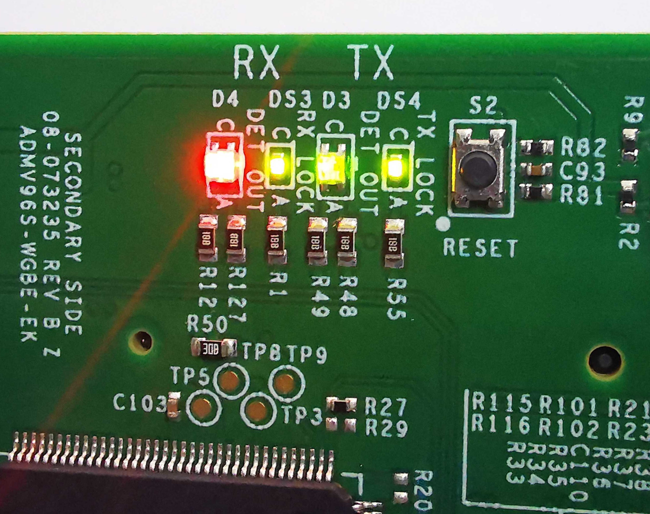
The 4 LED series at the top of the board convey the following information:
RX |
TX |
||
|---|---|---|---|
DET_OUT |
RX_LOCK |
DET_OUT |
TX_LOCK |
Lit (green or red) when RX autotuning is on, otherwise not lit. Green when RX_DET is within tolerance of the target. Red when RX_DET is not within tolerance of the target. |
Lit when RX VCO has locked. |
Lit (green or red) when TX autotuning is on, otherwise not lit. Green when TX_DET is within tolerance of the target. Red when TX_DET is not within tolerance of the target. |
Lit when TX VCO has locked. |
The following examples shows a board that has TX and RX VCO’s locked, TX and RX autotuning on, TX_DET within tolerance of target but the firmware can’t keep RX_DET within tolerance of target. To force this error, one of the boards facing each other was unplugged so the photographed board was trying to maximize the RX gains to receive something meaningful. But if there is no incoming signal, gain changes cannot possibly affect RX_DET so the firmware lights up the LED in red.
The RJ45 connector also has embedded LED’s. The top left one lights up green when the ADIN1300 has connected to another PHY over the Ethernet cable. This LED is briefly turned off when there is activity on the Ethernet cable essentially blinking it. So a blinking top left LED means both the Ethernet link is up and there is ongoing activity. The top right LED conveys link speed information and is turned off when link speed is 10 Mbps, lit green for 100 Mbps and lit amber when speed is 1000 Mbps.
EEPROM
The 24LC32A EEPROM has 32Kb memory capacity (4 KB) and is connected to an I2C bus. The firmware uses the EEPROM to store non-volatile parameters to be loaded at boot.
In order not to waste space, and to make sure future iterations of the firmware may use areas of the EEPROM that are currently unused, a design decision had to be made from the start, as to what size a non-volatile parameter set should have. A reasonable size of 256 bytes was chosen, which makes it possible to fit 16 such parameter sets into the memory.
Address |
Name |
Size |
|---|---|---|
0x0 |
NVMP1 |
256 |
0x100 |
Reserved |
3584 |
0xF00 |
Factory defaults |
256 |
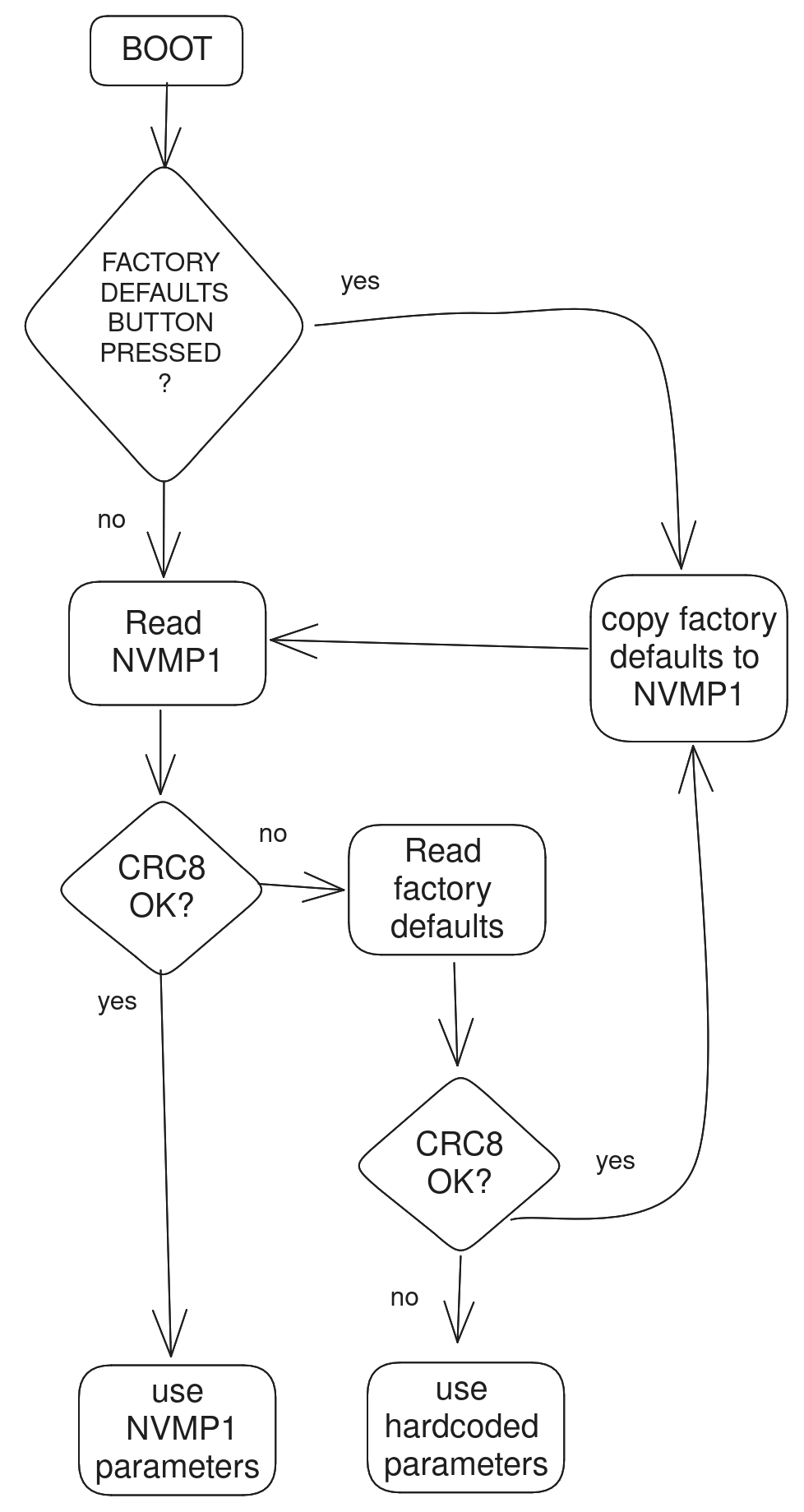
Two such areas are currently used by the firmware, one is the NVMP1 area which is the active configuration loaded at boot and the other one is the factory defaults configuration which can be copied into the active configuration with a certain procedure.
The 0x100 to 0x3FF memory area is not used.
Each NVMP area has 255 bytes of actual parameters and 1 last byte consisting of a CRC8 computed over the leading 255 bytes.
The CRC8 checksums are checked at boot and if they have been incorrectly written or tampered with, the parameters are not used. If no suitable parameters are found in NVMP1 or in the factory defaults area, a set of in-firmware hardcoded parameters are used for the boot.
Resetting to factory defaults
To explicitly reset to factory defaults, click the S3 button, keep it pressed and click the S2 button briefly. The four LED’s will blink 10 times for about 3 seconds to confirm the reset to factory defaults has completed.
Production firmware and provisioning
There are two versions of the firmware that are for normal and production use.
The normal firmware is the one that runs on the hardware, provided the hardware had gone through the production process fully. The production process has 3 main steps: actual hardware production, provisioning and testing.
The production firmware is a variant that has the following extra features:
It disregards whatever is in the EEPROM and loads up with hardcoded parameters.
It allows writing of the factory defaults area of the EEPROM by exposing the
mwc.save_defaultsattribute.It allows provisioning by allowing the change of the serial number (
mwc.hw_serial,mwc.carrier_serial), revision (mwc.hw_version,mwc.carrier_version) and model name (mwc.carrier_model) which all default to-when the device is not provisioned.
With a normal firmware, the device will not behave correctly if it was not
provisioned. The firmware needs valid parameters to operate correctly so having
- being displayed as carrier serial number is an indicator that the device
hasn’t somehow gone through the full production cycle that performs
provisioning.
Autonegotiation
The EVAL-ADMV96S-WGBE-EK1 is a system composed of two independent boards that connect to the outside world through Ethernet. The network infrastructure at the other end of the Ethernet cable is not known yet the system can detect its capabilities in terms of data bandwidth and dulplex mode due to autonegotiation signaling at physical layer (OSI model).
The system may be connected at any time to devices on a network that have different capabilities. The device at one end could be able to talk 100 Mbps half-duplex, the one at the other end could be capable of 1 Gbps full-duplex. In this scenario, the system needs to adapt for the weakest link and configure the 100 Mbps half-duplex speed at all levels, it’s the common denominator that allows the two devices to talk to each other.
Having two independent devices in a system, each running its own firmware, this could only be possible if there is some mechanism through which the devices could advertise speeds to one another. The wireless link carries SGMII interface and the SGMII itself has an autonegotiation mechanism through which a frame containing speed and duplex information can be passed on from one device to the other. The firmware uses this feature to propagate an Ethernet link speed change throughout the whole system.
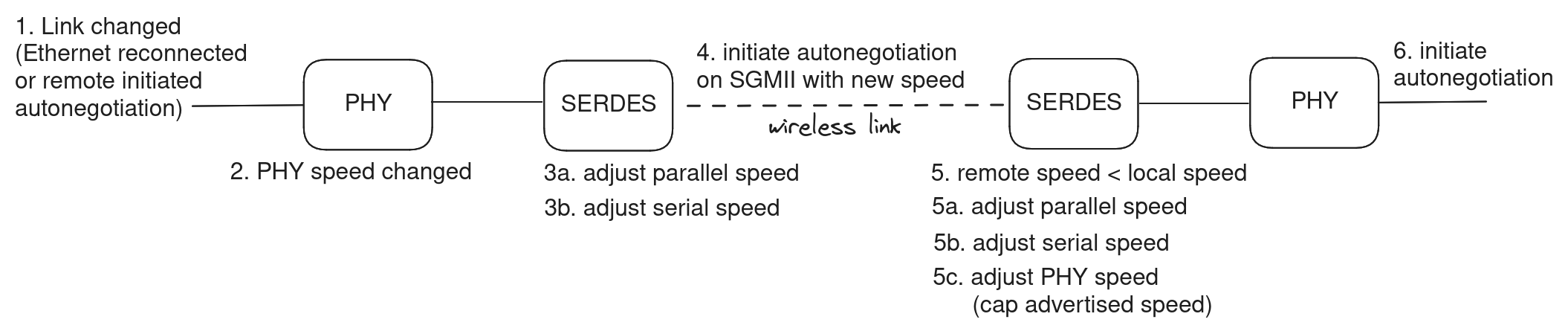
Steps 1-4 are executed in an interrupt service routine from the PHY when link status changes.
Steps 5-6 are executed in an interrupt service routine from the SERDES when new autonegotiation page was received.
To resume this section:
there is speed and duplex mode autonegotiation at Ethernet level
there is speed and duplex mode autonegotiation at SGMII level
the lowest advertised speed of a device in the system is propagated and the system subsequently works at that speed
Temperature compensated gains
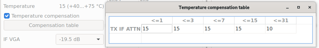
Due to reasons related to the transceiver hardware, the optimum gains at which it operates are temperature dependent. Affected gains are TX IF VGA, RX IF VGA and RX RF LNA. The optimum gains found through lab characterization are provided by Analog Devices.
The transceivers have a very coarse temperature sensor that is used by the firmware to look up gains in a lookup table. The default behavior of the firmware is to auto compensate gains for temperature using the factory default lookup tables.
You can disable auto compensation by unticking the checkbox, or you can keep it and adjust the tables to your liking.
TX temperature compensation table:
RX temperature compensation table:
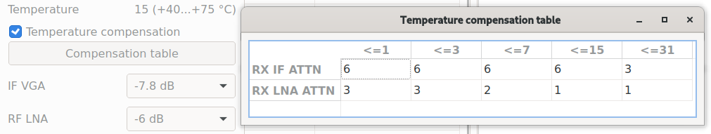
Raw Temp |
Range |
|---|---|
1 |
-40°C … -25°C |
3 |
-25°C … 10°C |
7 |
10°C … 40°C |
15 |
40°C … 75°C |
31 |
> 75°C |
P.I.D. controlled gains
TX_DET and RX_DET analog signals of the transceivers are sampled regularly by the embedded ADC of the microcontroller. They correspond to the TX and RX signal power and need to be kept in a certain sweetspot for proper operation of the wireless link.
The remaining gains, that aren’t temperature controlled, are the TX RF VGA and the RX BB (COARSE1, COARSE2 and FINE). By controlling these gains up and down, one can see a change in the RX and RX power detectors.
So we have a feedback loop and we can apply control theory on it in the form of a P.I.D. algorithm to keep the TX_DET and RX_DET in the sweetspot by having the algorithm tweak the gains. The implementation actually only uses the proportional and integral coefficients, essentially making this a P.I. control.
Every second the algorithm is run for several iterations until it settles on a resulting gain. There are two challenges:
Make it settle fast! We don’t care too much about overshoot, we care about settling fast because the algorithm is run on the main loop along with other things and we don’t want to block for too long.
Make it settle with as little gain changes as possible! Any gain change will momentarily mess with the signals being sent in that instant across the wireless link, so by minimizing the gain changes, we minimize the bit error rate throughout the whole system.
To illustrate how the algorithm works, here’s the result of a simulation with artificial perturbations at samples 100, 200, 300, and 400 in order to observe the characteristics of the control. The top part shows the output of the P.I. as an attenuation in steps between 0 and 31. The bottom part is a simulated RX_DET (mV) based on what attenuation the algorithm previously set.
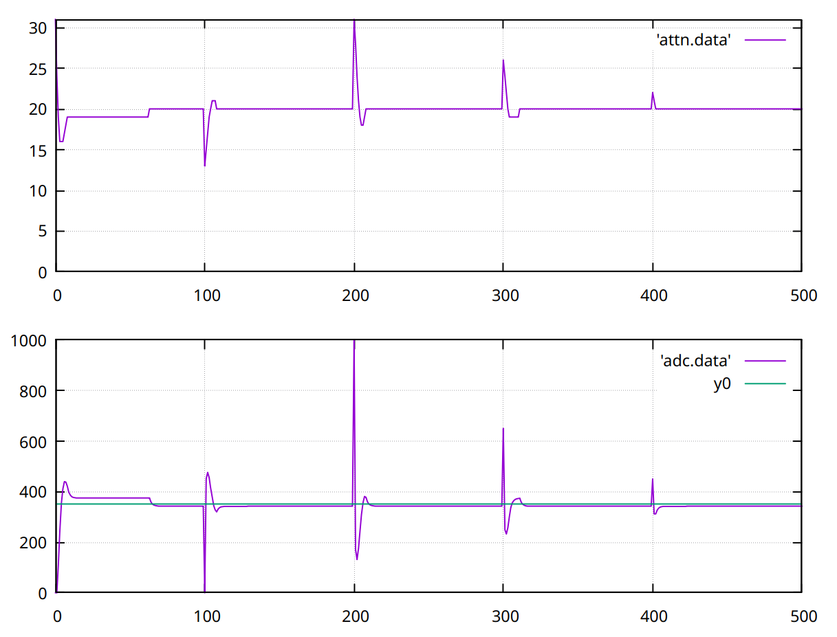
With the factory default settings, the algorithm finds the target within 10 iterations or less and does it with few gain changes addressing both of the above points. As with any P.I.D. algorithm, it’s possible that better behavior is achievable by experimentally fine tuning the coefficients but with the factory default coefficients and initial release implementation, the system achieves a bit error rate of less than 10E-10 for constant distance and across the whole -40°C to 80°C.