User guide
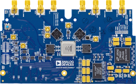
EVAL-AD9081 top view:
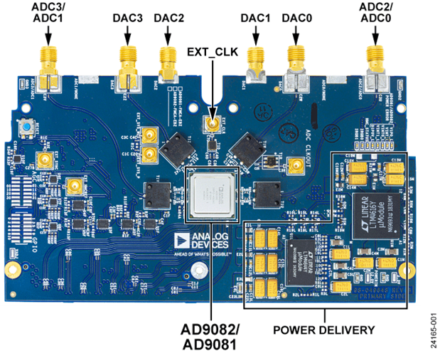
EVAL-AD9082 top view:
The complete user guide of the evaluation board can be found at AD9081/AD9082 Software Development User Guide, UG-1578 (Rev. A).
Hardware guide
Hardware configuration
Warning
When using A10SoC in your setup, the following reworks are required on the evaluation board:
To avoid using an external clock source and fully rely on the HMC7044 clock chip, rotate the C6D/C4D caps in C5D/C3D position (Please note: In the latest version of the board, this is now the default configuration, so this configuration step might not be needed anymore).
If LEDS V1P0_LED and VINT_LED are not on, please depopulate R22M and populate R2M
For the carrier, A10SoC, the following reworks are mandatory: FMC Pin Connection Configuration
Power supply
The power supply comes from the FMC connector, given by the FPGA.
The VADJ values can be checked out in the README.md file of each combination with an FPGA, at: projects/ad9081_fmca_ebz.
Schematic, PCB Layout, Bill of Materials
The schematic can be found at ad9081-mxfe-fmca-revc-eval-board-schematic.pdf.
The archive ad9081-ad9082.zip contains the design files for EVAL-AD9081 and EVAL-AD9082 evaluation boards.
Software guide
The evaluation board is supported with the Libiio library. This library is cross-platform (Windows, Linux, Mac) with language bindings for C, C#, Python, MATLAB, and others. Two easy examples that can be used with it are:
ADI IIO Oscilloscope
The IIO Oscilloscope is a cross-platform application for interfacing with IIO devices, enabling you to configure device parameters and visualize data.
Important
Make sure to download/update to the latest version of IIO Oscilloscope.
For Linux
Remote run on host
The IIO Oscilloscope application can be used to connect to another platform that has a connected device, to configure the device and read data from it. This application is not for performance testing, but rather showcasing the basic features.
Please see IIO Oscilloscope documentation for installation steps and more details.
Build and start osc on a network-enabled Linux host.
For Windows computers, open the application from the start menu.
Once the application is launched, go to Settings > Connect > URI and type “ip:” then the IP address of the target in the pop-up window. This IP can be found out with a command from the previous section of this documentation.
For no-OS
For connecting IIO Oscilloscope to no-OS applications, they need to be built with the IIOD=y flag. This way, the no-OS applications will run an IIO daemon that is awaiting connections from the IIO Oscilloscope.
As indicated in the boot log, the board runs an IIOD server over the serial (UART) connection.
Disconnect or close the serial terminal used to view the boot log.
Once done with the installation or an update of the latest IIO Oscilloscope, open the application.
Select the Serial backend and configure the connection with the settings shown at the end of the boot log.
Press Refresh to display the available IIO devices and press Connect.
Note
The serial port is the COM port on Windows or /dev/ttyUSBx on Linux.
About the IIO devices
Main receivers RX1, RX2, RX3, and RX4 are handled by the axi-ad9081-rx-hpc IIO device.
Channels:
IIO device channel:
axi-ad9081-rx-hpcReceiver inputs:
{
voltage0_i,voltage0_q}: RX1{
voltage1_i,voltage1_q}: RX2{
voltage2_i,voltage2_q}: RX3{
voltage3_i,voltage3_q}: RX4
Scopy
Scopy is a cross-platform software toolbox for interfacing with ADI devices, enabling you to configure device parameters, visualize data, and perform advanced signal analysis.