VCU118 Quick start
This guide provides quick instructions on how to setup the EVAL-AD9081 / EVAL-AD9082 on:
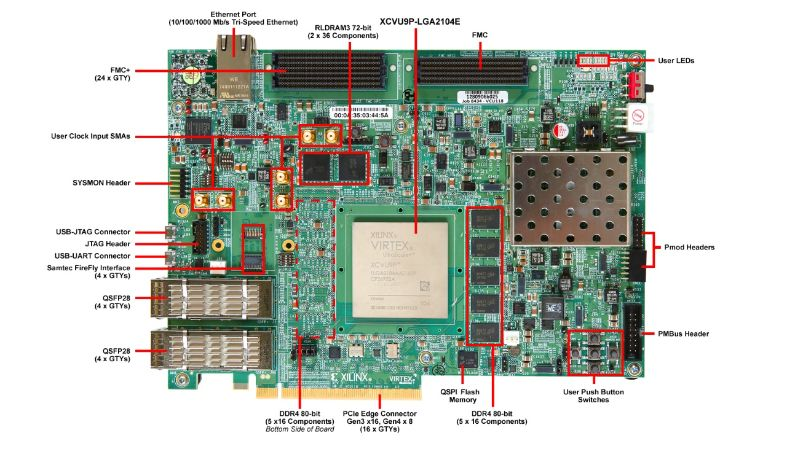
VCU118 FMC+
All the products described on this page include ESD (electrostatic discharge) sensitive devices. Electrostatic charges as high as 4000V readily accumulate on the human body or test equipment and can discharge without detection. Although the boards feature ESD protection circuitry, permanent damage may occur on devices subjected to high-energy electrostatic discharges. Therefore, proper ESD precautions are recommended to avoid performance degradation or loss of functionality. This includes removing static charge on external equipment, cables, or antennas before connecting to the device.
Using Linux as software
Necessary files
Note
The SD card includes several folders in the root directory of the BOOT partition. In order to configure the SD card to work with a specific FPGA board and ADI hardware, several files must be copied onto the root directory. Using the host PC, drag and drop the required files onto the BOOT partition, and use the EJECT function when removing the SD card from the reader.
The following files are needed for the system to boot:
HDL boot image:
BOOT.BINLinux Kernel image:
ImageLinux device tree:
system.dtb
They can either be taken from the SD card – already generated by us, or you can build them manually:
Instructions on how to choose the boot files from the SD card can be found in the Platform-Specific Manual Steps section from here: Hardware Configuration.
Instructions on how to manually build the boot files from source can be found here:
AD9081/AD9082/AD9986/AD9988 HDL project build documentation. More HDL build details at Build an HDL project.
Important
Some projects provide multiple devicetree files in the SD card’s boot folders. Make sure you select the devicetree that matches your specific use case.
Required Software
SD Card 16GB imaged with Kuiper (check out that guide on how to do it, then come back to this section)
A UART terminal (Putty/Tera Term/Minicom, etc.) with baud rate 115200 (8N1)
Required Hardware
AMD Xilinx VCU118 Rev 1.0 or later FPGA board and its power supply
EVAL-AD9081 / EVAL-AD9082 FMC evaluation board
SD card with at least 16GB of memory
2 x Micro-USB cable
LAN cable (Ethernet)
Signal generator
4x SMA cables
(Optional) USB keyboard & mouse and a HDMI compatible monitor
(Optional) 4 way splitter
More details as to why you need these, can be found at Prerequisites.
Testing
Creating the setup
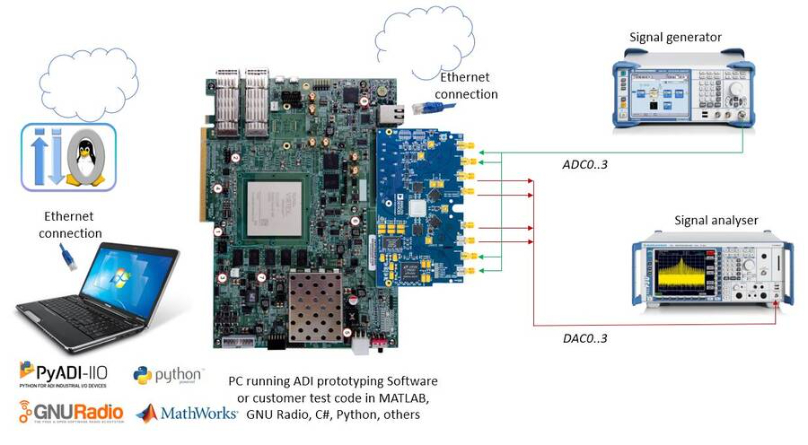
In the following example, we will make a physical loopback between the ADC and the DAC channels on the evaluation board, using SMA cables.
Follow the steps in this order, to avoid damaging the components:
Connect the SMA cables ADC0-DAC0, ADC1-DAC1, ADC2-DAC2, ADC3-DAC3
Connect the EVAL-AD9081 / EVAL-AD9082 FMC board to the VCU118 FMC+ socket
Insert SD card into the SD card socket on the FPGA
Configure VCU118 for SD card boot mode (mode SW6[3:1] switch in the position 1: Down, 2: Down, 3: Up, 4: Up )
Plug-in an Ethernet cable from your router/switch to the Ethernet port on the FPGA board
Connect USB UART (Micro-USB) to your host PC
(Optional) Connect a monitor to the FPGA by HDMI, and a mouse and a keyboard
Connect the power supply for the FPGA
Turn on the power switch on the FPGA board
Observe Kernel and serial console output messages on your terminal (use the first ttyUSB or COM port registered)
Boot messages
The following is what is printed in the serial console, after you have connected to the proper ttyUSB or COM port:
U-Boot 2018.01-21442-gf06dec3cab (Nov 10 2023 - 16:08:56 +0200) Xilinx ZynqMP VCU118 revA, Build: jenkins-development-build_uboot-6

I2C:   ready
DRAM:  4 GiB
Useful commands for the serial terminal
The below commands are to be run in the serial terminal connected to the FPGA.
To find out the IP of the FPGA board, run the following command and take the IP specified at “eth0 inet”:
~$
ifconfig
To see the IIO devices detected, run:
~$
iio_info | grep iio:device
    iio:device0: hmc7044
    iio:device1: axi-ad9081-tx-hpc (buffer capable)
    iio:device2: axi-ad9081-rx-hpc (buffer capable)
To see the EEPROM specifications, run:
~$
fru-dump -b /sys/bus/i2c/devices/15-0050/eeprom
To use the JESD204 status utility, run:
~$
jesd_status
All links should be in DATA without errors:
~$
jesd_status -s
(DEVICES) Found 2 JESD204 Link Layer peripherals
(0): axi-jesd204-rx/44a90000.axi-jesd204-rx  [*]
(1): axi-jesd204-tx/44b90000.axi-jesd204-tx
(STATUS)
Link is                      enabled
Link Status                  DATA
Measured Link Clock (MHz) 249.998
Reported Link Clock (MHz) 250.000
Measured Device Clock (MHz) 250.000
Reported Device Clock (MHz) 250.000
Desired Device Clock (MHz) 250.000
Lane rate (MHz)              10000.000
Lane rate / 40 (MHz)         250.000
LMFC rate (MHz)              7.812
SYSREF captured              Yes
SYSREF alignment error       No
SYNC~
(LANE STATUS)
Lane# 0 1 2 3
Errors 0 0 0 0
Latency (Multiframes/Octets) 1/22 1/20 1/25 1/21
CGS State DATA DATA DATA DATA
Initial Frame Sync                Yes    Yes    Yes    Yes
Initial Lane Alignment Sequence   Yes    Yes    Yes    Yes
To power off the system, run the following command, and wait for the final message to be printed, then power off the FPGA board from the switch as well.
~$
poweroff
To reboot the system, run:
~$
reboot
Important
Even thought this is Linux, this is a persistent file systems. Care should
be taken not to corrupt the file system – please shut down things, don’t
just turn off the power switch. Depending on your monitor, the standard
power off could be hiding. You can do this from the terminal as well with
sudo shutdown -h now or the above-mentioned command for powering
off.
Using no-OS as software
Necessary files
The following files are needed for the system to boot:
HDL boot file:
system_top.xsano-OS project: projects/ad9081
Instructions on how to build the boot files from source can be found here:
AD9081 no-OS Example Project. More no-OS build details at No-OS Build Guide.
AD9081/AD9082/AD9986/AD9988 HDL project. More HDL build details at Build an HDL project.
Required Software
AMD Xilinx Vivado and Vitis (downloading Vitis from here will include Vivado as well)
An UART terminal (Putty/Tera Term/Minicom, etc.), Baud rate 115200 (8N1)
Required Hardware
AMD Xilinx VCU118 Rev 1.0 or later FPGA board and its power supply
EVAL-AD9081 / EVAL-AD9082 FMC evaluation board
2x Micro-USB cables, one for UART and one for JTAG
(Optional) USB keyboard & mouse and a HDMI-compatible monitor
More details as to why you need these, can be found at Prerequisites.
Testing
Creating the setup
Follow the steps in this order, to avoid damaging the components:
Connect the EVAL-AD9081 / EVAL-AD9082 FMC board to the VCU118 FMC+ socket
Configure VCU118 for SD card boot mode (mode SW6[3:1] switch in the position 1: Down, 2: Down, 3: Up, 4: Up )
Connect USB UART (Micro-USB) to your host PC
Connect USB JTAG (Micro-USB) to your host PC
(Optional) Connect a monitor to the FPGA by HDMI, and a mouse and a keyboard
Turn on the power switch on the FPGA board
Observe console output messages on your terminal (use the first ttyUSB or COM port registered)
Console output
The following is what is printed in the serial console, after you have connected to the proper ttyUSB or COM port:
Xilinx Microblaze First Stage Boot Loader