ADRD8012-01Z
FPGA-based 8 x GMSL2 cameras to 10 Gb Ethernet Edge Compute Platform
Overview
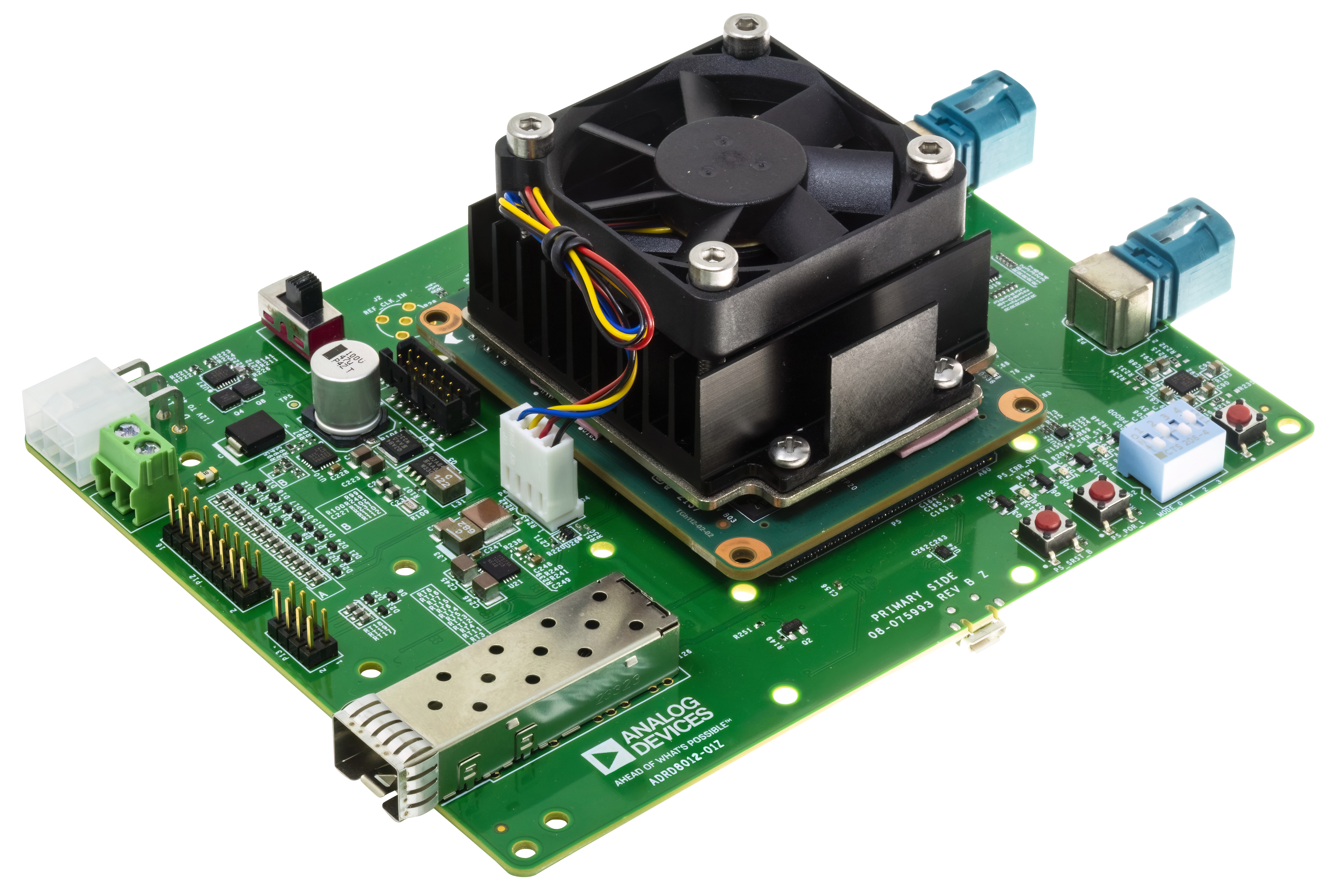
ADRD8012-01Z is an edge compute platform enabling low latency data transfer from two Gigabit Multimedia Serial Link™ (GMSL) deserializers (resulting in an example of up to 8 GMSL2-enabled camera modules) on to a 10 Gb Ethernet link. The target applications include autonomous robots and vehicles where machine vision and real-time sensor fusion is critical. Some of the main features and benefits include:
2x GMSL2 deserializers with up to 6 Gbps/SerDes link
10 GbE-capable SFP+ connector
Precision Time Protocol (PTP) for synchronization with host systems and other edge devices
Embedded processing capabilities using the on-board AMD Kria K26 System-on-Module
ROS2 compliant video streaming design
Open-source embedded Linux software and FPGA design
Advanced camera triggering functions and control features
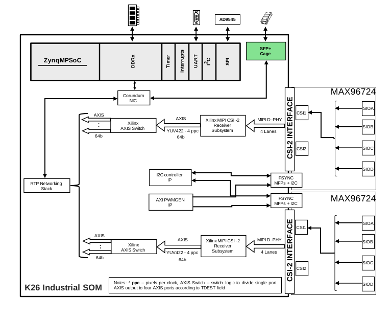
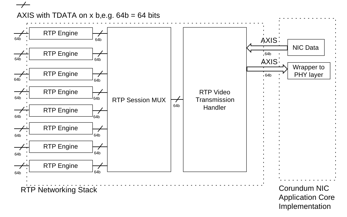
The block design and the RTP networking stack made using the FPGA region are presented below:
Specifications
Interfaces |
|
|---|---|
SFP+ |
Supports 10 Gb Ethernet with IEEE 1588 hardware timestamping |
RS-232 |
Serial interface for connecting UART peripherals, e.g., GNSS devices |
I/O |
16 general purpose I/O pins with software configurable functionality, 3.3V voltage level |
GMSL |
2x Quad Fakra connectors supporting 8 x GMSL2 camera interfaces |
Processing |
|
AMD K26 |
Industrial grade AMD K26 SoM |
Power & Thermal |
|
Power Supply |
Input voltage: 9V to 48V DC at 24W max |
Operating Temperature |
-40°C to 60°C |
Software |
|
Operating System |
Linux OS |
Network data protocol |
Open-sourced FPGA-accelerated Real-Time Transport for uncompressed video over UDP/IPv4 implementation |
System Setup & Evaluation
Required Hardware
1 x ADRD8012-01Z
Up to 8 x Fakra cables
2 x Quad-based mini-Fakra cables
1 x 16 GB SD card
1 x PC with 10 GbE NIC
1 x SFP+ Ethernet cable
Example GMSL2 camera options
up to 8 x Tier IV C1 cameras
up to 4 x Tier IV C2 cameras
SD Card Image
SD card image that contains example setups using previously mentioned GMSL2-enabled cameras
After downloading the file, extract the compressed image and write it to the SD card using Balena Etcher or Win32-Disk-Imager.
More details on how to extract a compressed image and write it on the SD card on Linux and Windows can be found here: Writing an image onto the SD card
System Setup
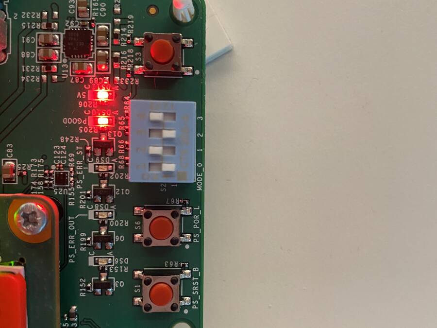
In order to boot using SD card, you will need to set the boot mode’s switches to the corresponding position, as indicated in the following image:
Connect the Quad-based mini-Fakra cables to the corresponding connectors on the board. These will connect the cameras to the corresponding deserializers.
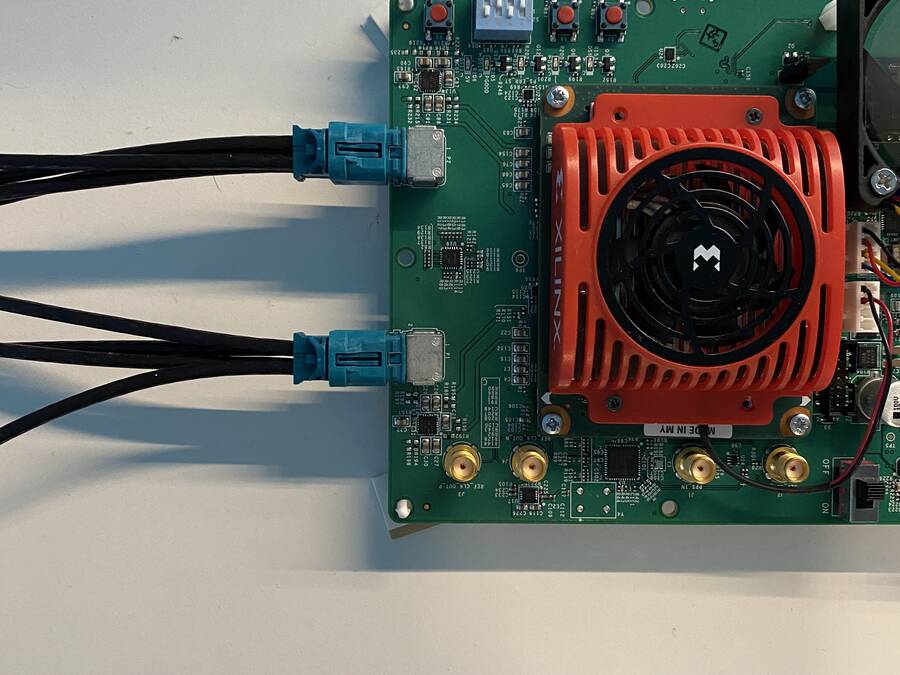
Figure 5 Quad mini-Fakra cabbles connection to board’s deserializers
Connect an SFP+ cable to the corresponding SFP+ port on the board.
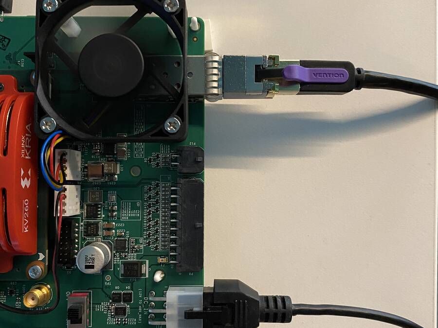
Finally, you will need to connect a USB/micro-USB cable to the micro-USB port located on the board. After that, you will be able to connect to the first USB COM port that appears on the serial terminal, with a baud rate of 115200. Besides this wired connection, after the Linux system on the board is completely initialized, you will be able to use the network-related connection through the 10 GbE interface (eth0 on the board) and leveraging ssh SW support.
Note
Ubuntu credentials
username:analog
password:analog
#eth0 - 10G ethernet interface
~$
ls -l /sys/class/net/
total 0
lrwxrwxrwx 1 root root 0 Mar 20 16:32 eth0 -> ../../devices/platform/axi/a0000000.ethernet/net/eth0
lrwxrwxrwx 1 root root 0 Mar 20 16:32 lo -> ../../devices/virtual/net/lo
lrwxrwxrwx 1 root root 0 Mar 20 16:32 sit0 -> ../../devices/virtual/net/sit0
Important
Both server and client should have the same MTU. Default camera setup is 4 x Tier IV C1 on P1 deserializer (connected to CSI-2 RX subsystem 0). In case of Intel RealSense D457 camera, only the example setup with 1 camera module on P1 is present, and it contains the hardcoded 0/1 sensors enabled for virtual channels 0 and 1 (as these are streaming RAW color format - UYVY).
#Set the eth0's MTU and IP address
~$
sudo ip link set mtu 9000 dev eth0 up
~$
sudo ifconfig eth0 10.42.0.1
~$
ip a
1: lo: <LOOPBACK,UP,LOWER_UP> mtu 65536 qdisc noqueue state UNKNOWN group default qlen 1000
    link/loopback 00:00:00:00:00:00 brd 00:00:00:00:00:00
    inet 127.0.0.1/8 scope host lo
        valid_lft forever preferred_lft forever
    inet6 ::1/128 scope host
        valid_lft forever preferred_lft forever
2: sit0@NONE: <NOARP> mtu 1480 qdisc noop state DOWN group default qlen 1000
    link/sit 0.0.0.0 brd 0.0.0.0
3: eth0: <BROADCAST,MULTICAST,UP,LOWER_UP> mtu 9000 qdisc mq state UP group default qlen 1000
    link/ether a2:78:c4:14:da:c2 brd ff:ff:ff:ff:ff:ff
    inet 10.42.0.1/8 brd 10.255.255.255 scope global eth0
        valid_lft forever preferred_lft forever
    inet6 fe80::a078::c4ff:fe14:dac2/64 scope link
        valid_lft forever preferred_lft forever
#(Optional, if you don't know the destination MAC address of the remote side - the NIC of the PC
#which is locally connected to the board)
#Ping the PC's IPv4 address
~$
ping <board-ipv4-address>
#Check the ARP table of the board's NIC
~$
arp -a
#You will see the matches between IPv4 and MAC addresses
#IPv4 MAC
FPGA-accelerated RTP networking stack setup
#Configure the instantiated RTP engines and RTP session mux logic
#using the files created by the sysfs implementation - which represent
#configurable fields of the implemented protocols
#RTP engines - devices present in /sys/devices/
#e.g. (L2) - MAC sublayer of Ethernet v2 standard
~$
echo 0xaabbccddeeff > dest_mac_address
~$
echo 0x010203040506 > src_mac_address
#e.g. (L3) - IPv4
~$
echo 0x0a2a0014 > dest_ipv4_address
~$
echo 0x0a2a0018 > src_ipv4_address
#e.g. (L4) - UDP
~$
echo 5004 > dest_udp_port
~$
echo 5004 > src_udp_port
#e.g. (L7) - RTP
~$
echo 1920 > num_pixels_per_line
~$
echo 1280 > num_lines
#In addition, the video format can be converted from YUYV to UYVY (as ordering methods
#in YUV422)
~$
echo 1 > convert_yuyv_to_uyvy
#Start the video transmission using the FPGA-accelerated RTP stack by setting the
#start_transfer bit of the RTP session mux driver
~$
echo 1 > start_transfer
Video subsystem configuration and streaming startup
#Configure the video image format for GMSL SerDes/MIPI CSI-2 receiver subdevices and FPS of the camera
#module
#some of the Tier IV C1,C2 and RealSense D457 setups contain pre-implemented scripts for the configuration
#for the subdevs of the instantiated media devices. The name included in media_cfg_X is related to the
#sensor - Tier IV C1 contains isx021, C2 - imx490 and the d457 remains the same as the camera name
~$
cd /home/analog/config_streaming
/home/analog/config_streaming$
./media_cfg_isx021_4p1.sh
#Start the transmission from the sensor devices
/home/analog/config_streaming$
cd /home/analog/config_streaming
#(depending on the number of used deserializers - each one will instantiate one video and media device)
/home/analog/config_streaming$
./start_streaming_TierIV_C1_videodev0_1
Note
The video streaming using the FPGA-accelerated RTP stack is started automatically when the RTP engines and session mux instances are configured as indicated before. On the other side, the streaming from the sensors is realized using the v4l2-ctl command executed on the corresponding video devices. The v4l2-related commands depending on the hardware connectivity are present in this SW configurations for video subsystem and streaming-related section. In order to stop all this processes generated by the streaming-related scripts, you can use the Linux pidof command to see what are the IDs of this v4l2-ctl-related instaces, and after that kill these ones by using Linux kill command, in the following way:
#Pidof output when having 2 video devices on which the streaming is started
~$
pidof v4l2-ctl
~$
800 799
~$
sudo kill 800 799
The video streaming is done using the previously configured UDP source/destination ports.
Remote target setup
To decode the RTP-based video streaming from the ADRD8012-01z system, you can use various video streaming frameworks which supports the RFC-compliant RTP for uncompressed video standard (RFC4175). This section presents the example setup using the GStreamer framework running on an Linux distro. Depending on the Linux distribution of your x86/arm64 workstation, you can install Gstreamer by using the corresponding package manager. For example, on Ubuntu you can use the following command:
~$
sudo apt-get install gstreamer1.0-tools gstreamer1.0-plugins-base
gstreamer1.0-plugins-good gstreamer1.0-plugins-bad
gstreamer1.0-plugins-ugly gstreamer1.0-libav
More details about Gstreamer installation can be found here.
The following examples serves as commands used to decode the RTP-based video streaming from the cameras from 1/2 deserializers [for a Tier IV C1 setup]
Single Deserializer (4 C1 cameras)
If destination UDP ports were set to 5004-5007, use the following commands for 4 Tier IV C1s [1920x1280]:
On remote target
~$
gst-launch-1.0 udpsrc caps="application/x-rtp, sampling=YCbCr-4:2:2, \
depth=(string)8, width=(string)1920, height=(string )1280" port="5004" ! \
rtpvrawdepay ! videoconvert ! fpsdisplaysink video-sink=xvimagesink \
text-overlay=true sync=false
~$
gst-launch-1.0 udpsrc caps="application/x-rtp, sampling=YCbCr-4:2:2, \
depth=(string)8, width=(string)1920, height=(string )1280" port="5005" ! \
rtpvrawdepay ! videoconvert ! fpsdisplaysink video-sink=xvimagesink \
text-overlay=true sync=false
~$
gst-launch-1.0 udpsrc caps="application/x-rtp, sampling=YCbCr-4:2:2, \
depth=(string)8, width=(string)1920, height=(string )1080” port="5006" ! \
rtpvrawdepay ! videoconvert ! fpsdisplaysink video-sink=xvimagesink \
text-overlay=true sync=false
~$
gst-launch-1.0 udpsrc caps="application/x-rtp, sampling=YCbCr-4:2:2, \
depth=(string)8, width=(string)1920, height=(string )1280" port="5007" ! \
rtpvrawdepay ! videoconvert ! fpsdisplaysink video-sink=xvimagesink \
text-overlay=true sync=false
Two Deserializers (8 C1 cameras)
If destination UDP ports were set to 5004-5011, use the following commands for 8 Tier IV C1s [1920x1280]:
On remote target
~$
gst-launch-1.0 udpsrc caps="application/x-rtp, sampling=YCbCr-4:2:2, \
depth=(string)8, width=(string)1920, height=(string )1280" port="5004" ! \
rtpvrawdepay ! videoconvert ! fpsdisplaysink video-sink=xvimagesink \
text-overlay=true sync=false
~$
gst-launch-1.0 udpsrc caps="application/x-rtp, sampling=YCbCr-4:2:2, \
depth=(string)8, width=(string)1920, height=(string )1280" port="5005" ! \
rtpvrawdepay ! videoconvert ! fpsdisplaysink video-sink=xvimagesink \
text-overlay=true sync=false
~$
gst-launch-1.0 udpsrc caps="application/x-rtp, sampling=YCbCr-4:2:2, \
depth=(string)8, width=(string)1920, height=(string )1280" port="5006" ! \
rtpvrawdepay ! videoconvert ! fpsdisplaysink video-sink=xvimagesink \
text-overlay=true sync=false
~$
gst-launch-1.0 udpsrc caps="application/x-rtp, sampling=YCbCr-4:2:2, \
depth=(string)8, width=(string)1920, height=(string )1280" port="5007" ! \
rtpvrawdepay ! videoconvert ! fpsdisplaysink video-sink=xvimagesink \
text-overlay=true sync=false
~$
gst-launch-1.0 udpsrc caps="application/x-rtp, sampling=YCbCr-4:2:2, \
depth=(string)8, width=(string)1920, height=(string )1280" port="5008" ! \
rtpvrawdepay ! videoconvert ! fpsdisplaysink video-sink=xvimagesink \
text-overlay=true sync=false
~$
gst-launch-1.0 udpsrc caps="application/x-rtp, sampling=YCbCr-4:2:2, \
depth=(string)8, width=(string)1920, height=(string )1280" port="5009" ! \
rtpvrawdepay ! videoconvert ! fpsdisplaysink video-sink=xvimagesink \
text-overlay=true sync=false
~$
gst-launch-1.0 udpsrc caps="application/x-rtp, sampling=YCbCr-4:2:2, \
depth=(string)8, width=(string)1920, height=(string )1280" port="5010" ! \
rtpvrawdepay ! videoconvert ! fpsdisplaysink video-sink=xvimagesink \
text-overlay=true sync=false
~$
gst-launch-1.0 udpsrc caps="application/x-rtp, sampling=YCbCr-4:2:2, \
depth=(string)8, width=(string)1920, height=(string )1280" port="5011" ! \
rtpvrawdepay ! videoconvert ! fpsdisplaysink video-sink=xvimagesink \
text-overlay=true sync=false
User Guides
Help and Support
For questions and more information, please visit the EngineerZone.