EV-CATTLETAG-ARDZ
Sensor for Livestock Tracking and Health Monitoring
Overview
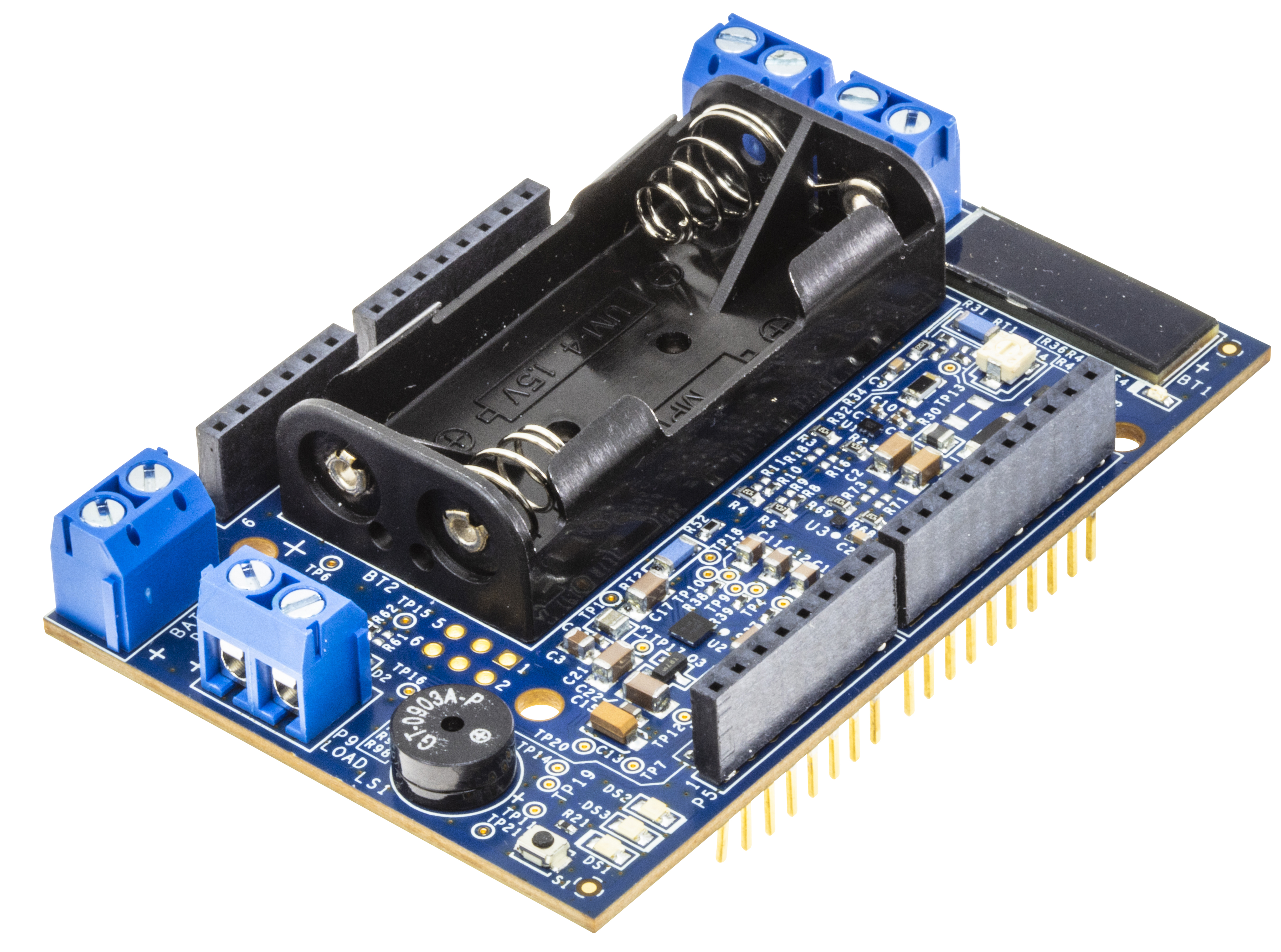
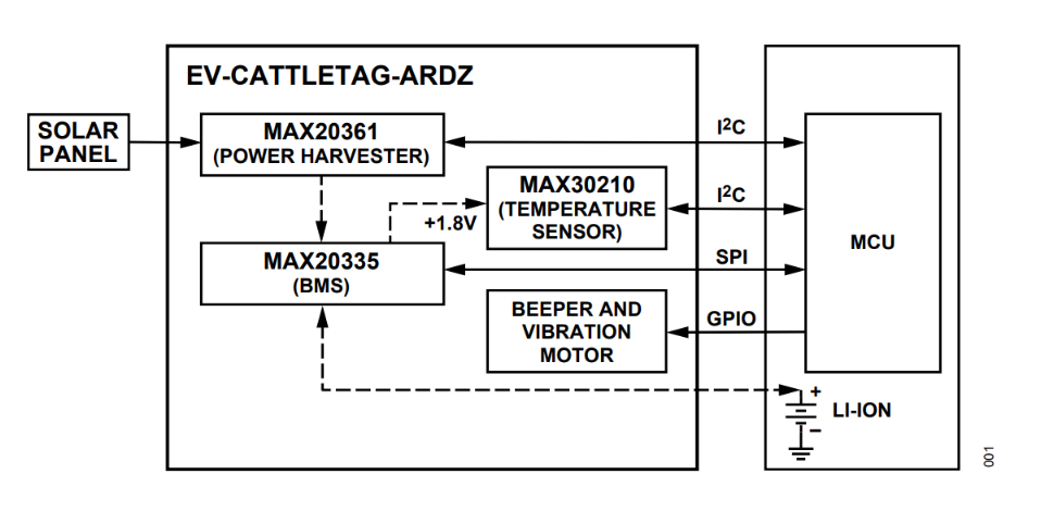
The EV-CATTLETAG-ARDZ is an Arduino board with a fully integrated solution for harvesting energy from single-/multicell solar sources. The device includes battery chargers for small lithium-ion systems, and a digital temperature sensor for applications such as Wearables and IoT. The system is consisting of a MAX20361 power harvester, MAX20335 BMS, and a MAX30210 temperature sensor and a buzzer with an option for vibration motor.
Features
Monitors the health and vitality of livestock in real-time, enabling farmers to quickly treat animals and prevent the spread of illness or disease.
Tracks grazing animals to prevent loss and to identify grazing patterns.
Gathers and analyzes historical data to identify trends in cattle health or to track the spread of illness.
Monitors readiness to mate or give birth, preventing the loss of new calves and optimizing breeding practices.
Applications
Asset location
Asset recovery
Asset traceability
Inventory management
Asset loss and theft prevention
System Architecture
Hardware Design
Components and Connections
Power Supply
When using the board, the power supply may come from different sources, and these are listed below:
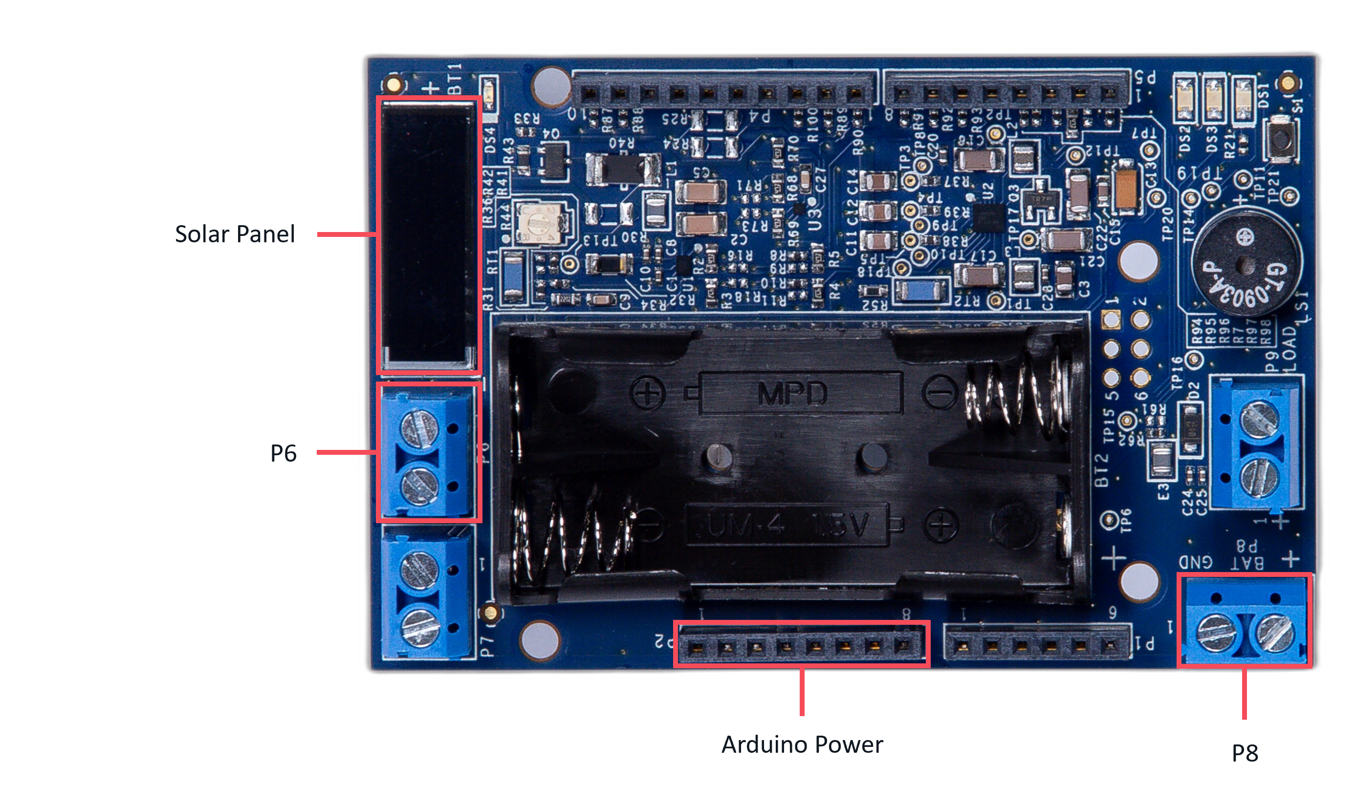
Solar Panel - use to recharge the lithium-ion connected to either P8 or to the 2x AAA battery. An example of a probe that can be used is a product from AnySolar and its datasheet can be found here.
P6 Terminal block - external power source (e.g., solar panel)
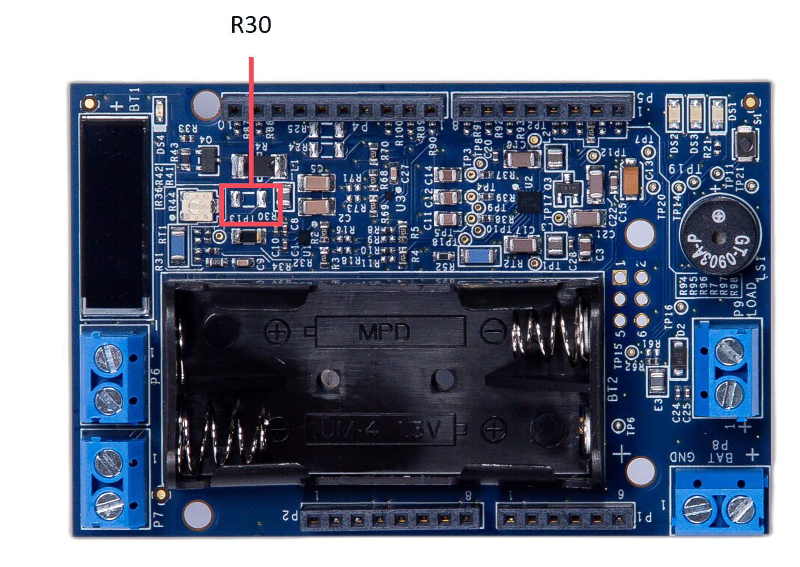
Note
When using an external power source, it is required to disconnect the on-board solar panel by removing the resistor R30.
P8 Terminal block - external power supply, between 3V to 4.2V allowable input
Battery holder - 2xAAA battery is required.
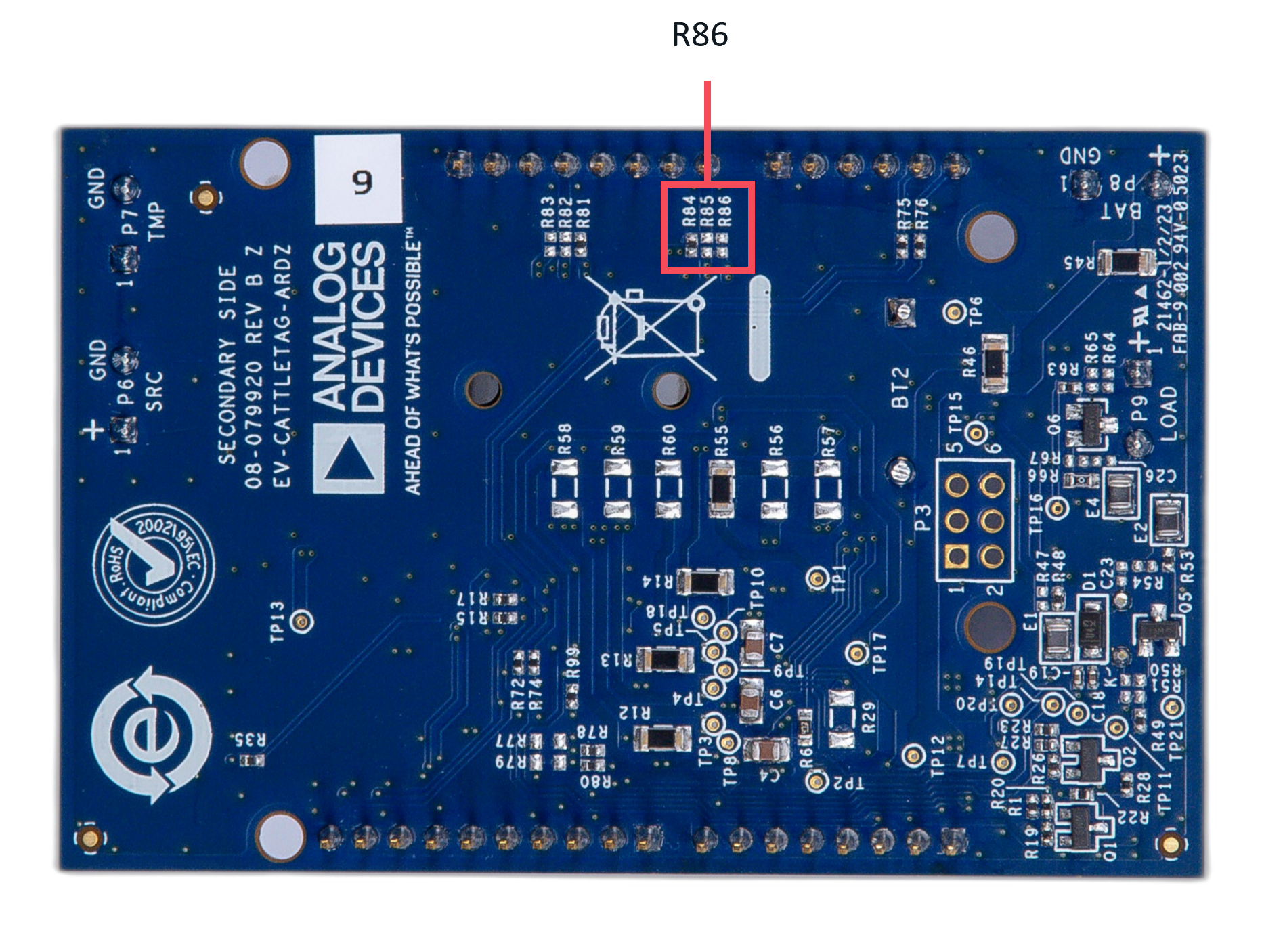
Arduino Power - external power supply that comes directly from the host board it is connected to.
Note
When power supply directly from the host board is used, it is required to remove the R84 resistor and placed a 0Ω resistor at R86.
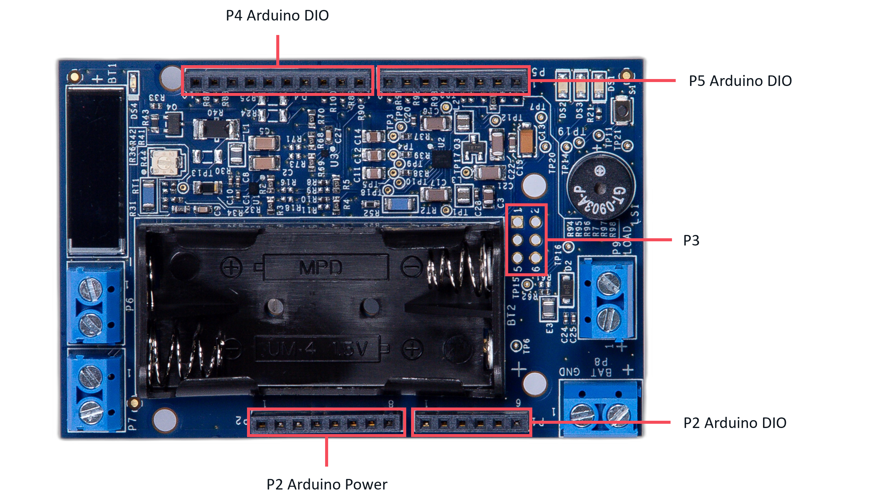
Digital Interface (Arduino)
The Arduino interface is a standardized digital interface for various digital communication protocols such as SPI, I2C, and UART. These interface types were standardized by Arduino, which is hardware and software company. Complete details on the PMOD specification can be found here.
The pin map for the Arduino pins is described in the table and its schematic diagram below.
Applications
The EV-CATTLETAG-ARDZ can be used with the MAX32670-LR-ARDZ Base Board, which is a long-range wireless radio development platform based on MAX32670 ultralow power Arm Cortex-M4 microcontroller and LR1110 RF transceiver.
Using these platforms together enables users to design solutions based on low-power, long range proprietary radio communication technique that is suitable for customized heat/flow meters.
To learn more about the Long Range Wireless Radio solution developed by Analog Devices, visit the AD-MAX32LRWISE-SL Long Range Wireless Radio Development Kit User Guide.
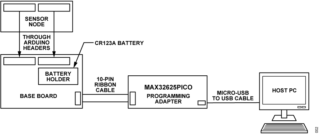
System Setup
PHASE 1: Hardware Setup
Note that this setup only applies for MAX32670-LR-ARDZ Base Board. Users may use a different base board or microcontroller, however the firmware built for this demo application cannot be used as this is specifically designed for the MAX32670-LR-ARDZ.
Equipment Needed
One (1) MAX32670-LR-ARDZ Base Board
One (1) EV-CATTLETAG-ARDZ Sensor Node
One (1) MAX32625PICO Rapid Development Platform with 10-pin ribbon cable with firmware image: MAX32625PICO Firmware Image for MAX32670
One (1) CR123A Battery or any equivalent external DC power supply (+3V to +4.7V). Note that this is not included in the kit
One (1) Micro USB to USB cable
Host PC (Windows 10 or later)
Insert one CR123A battery (3V to 4.7V) into the battery holder (BT1 connector) of the MAX32670-LR-ARDZ Base Board.
Make sure to check for the battery polarity in the BT1 connector, refer to the figure below. The DS3 LED will light up indicating that you have inserted the battery correctly and that power is provided in the base board.
Connect the EV-CATTLETAG-ARDZ Sensor Node to the MAX32670-LR-ARDZ Base Board by aligning the corresponding Arduino headers on each board.
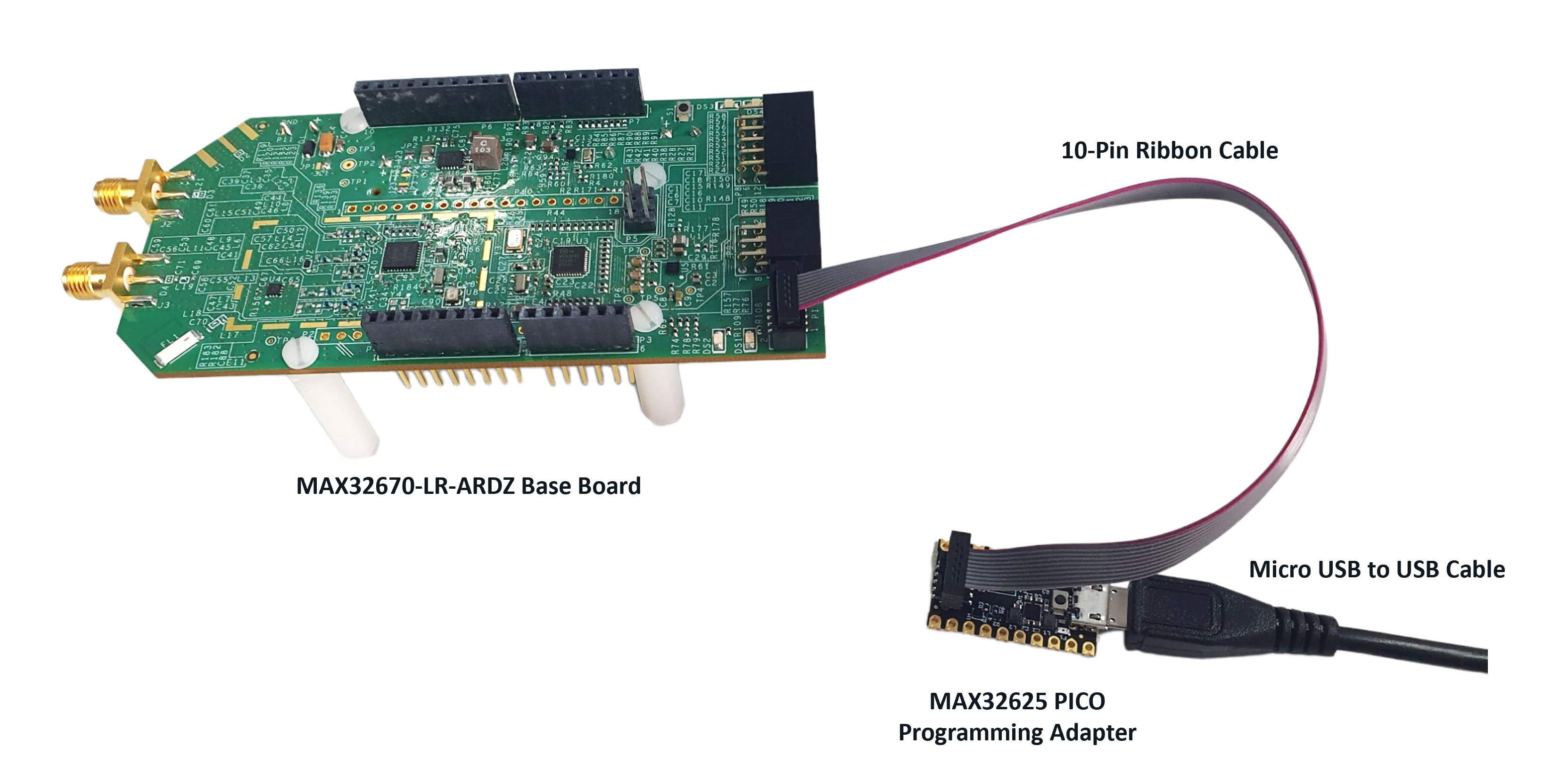
Connect the MAX32625PICO programming adapter to the MAX32670-LR-ARDZ Base Board through the 10-pin ribbon cable.
Make sure that the MAX32625PICO programming adapter has been flashed with the correct image before connecting it to the MAX32670-LR-ARDZ Base Board. If you do not know how to load the image, click on the instructions below:
How to flash the firmware image in the MAX32625PICO
Download the firmware image: MAX32625PICO Firmware Image for MAX32670
Do not connect the MAX32625PICO to the MAX32670-LR-ARDZ Base Board yet.
Connect the MAX32625PICO to the Host PC using the micro USB to USB cable.
Press the button on the MAX32625PICO. (Do not release the button until the MAINTENANCE drive is mounted).
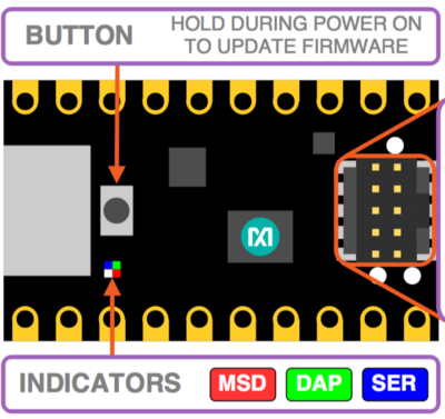
Release the button once the MAINTENANCE drive is mounted.
Drag and drop (to the MAINTENANCE drive) the firmware image.
After a few seconds, the MAINTENANCE drive will disappear and be replaced by a drive named DAPLINK. This indicates that the process is complete, and the MAX32625PICO can now be used to flash the firmware of the MAX32670-LR-ARDZ Base Board.
Connect the MAX32625PICO programming adapter to the Host PC using the micro USB to USB cable.
Once you have completed this setup, proceed to PHASE 2 found in ADI Long Range Wireless Radio Software User Guide.
Resources
Design and Integration Files
Download
EV-CATTLETAG-ARDZ Design Support Package Rev. C
Schematic
Bill of Materials
Layout
Fabrication Files
Help and Support
For questions and more information about this product, connect with us through the Analog Devices Engineer Zone.