Hardware User Guide
Introduction
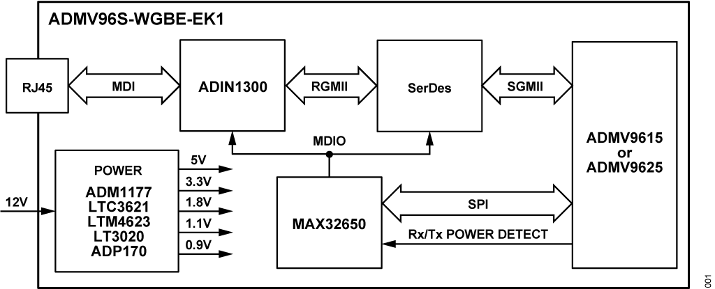
The ADMV96S-WGBE-EK1 is a complete evaluation and prototyping system for 60 GHz short data links. It consists of a pair of receiver and transmitter boards with a 1 Gbps Ethernet interface on each side of the wireless link.
The evaluation kit enables customers to evaluate the technology at its full potential, configure the system for their particular applications to mitigate risks of operation failure, provide a proven recipe to use for final product development. The users to set up a 60 GHz short range data link using standard interfaces. For programming and configuring the data link, the user has software tools available for download.
The 60 GHz wireless link is implemented by the ADMV9615 and ADMV9525 modules. These are coupled with a SerDes device which translates the modules’ SGMII interface to RGMII so that it can be connected to an ADIN1300 industrial low latency and low power 1 Gbps Ethernet PHY. This enables each side of the wireless link to act as an Ethernet port and essentially create a seamless wire-like connection between two ends of an Ethernet cable.
The on-board MAX32650 ultralow power ARM® Cortex®-M4 microcontroller controls the system’s operation and implements the algorithms to configure the wireless link in real time so that optimal link quality is constantly maintained over temperature and various operating conditions. An open-source software stack is provided for firmware development as well as reference applications. The MAX32650 can be programmed through a programming port which can also be used for firmware debugging.
Evaluation Kit Contents
1x ADMV96S-WGBE-EK1 populated with ADMV9615 and heatsink
1x ADMV96S-WGBE-EK1 populated with ADMV9625 and heatsink
2x 12V 1.5A power supplies (VEL36US120-US-JA 12V, 36W AC/DC external wall mount Class II adapter)
2x USB-A to micro-USB cables
2x MAX32625PICO programmer
1x rail
Setting up the Hardware
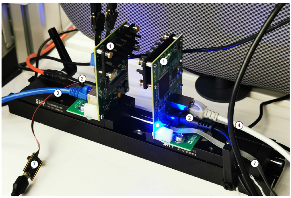
Set up the hardware following these steps:
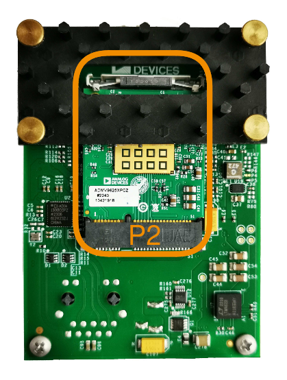
For both boards, make sure the S1 switch is in a position that corresponds to the label printed on the module inserted in P2. The wireless link will only work between an ADMV9615 and an ADMV9625 with the S1 switches correctly configured.
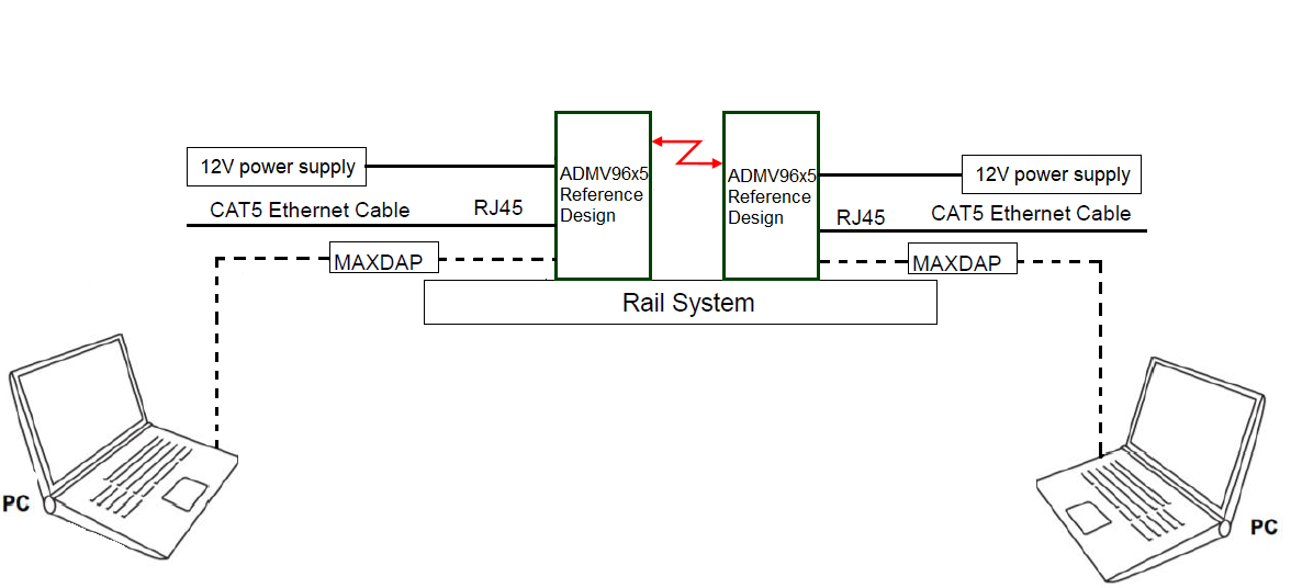
Mount the ADMV9615 and ADMV9625 assemblies onto the rail system as pictured
Connect CAT5 RJ45 Ethernet cables (3, 4) through the system (from a PC to a router, from a PC to another PC, etc.)
Optionally, connect the MAXDAP programmers (7) using micro-USB cables to your PC’s COM ports to be able to use the Wethlink GUI application*
Connect the 12V power supplies (2)
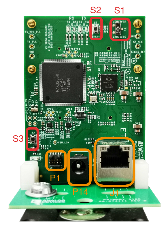
Connectors and Buttons
Item Name |
Function/Description |
|---|---|
P1 |
MAXDAP ADAPTER |
P2 |
ADMV9615 or ADMV9625 connector |
P14 |
12V DC Jack connector |
J1 |
RJ-45 Ethernet connector |
S1 |
ADMV9615/ADMV9625 switch, must be manually set to correct position when inserting a transceiver module in P2 |
S2 |
Reset button, pressing it resets the MAX32650 |
S3 |
Reset to factory defaults, may be pressed during a reset (S2) to reset the board to factory default settings. |
Power Supply
The ADMV96S-WGBE-EK1 kit contains two VEL36US120-US-JA 12V, 36W AC/DC external wall mount (Class II) adapters. The board has a DC barrel jack connector dedicated for power supply with the following mating dimensions: 2.10mm ID (0.083“) and 5.50mm OD (0.217”). It accepts voltages between 4V and 16V, but it is recommended to be supplied with 12V.
Power tree
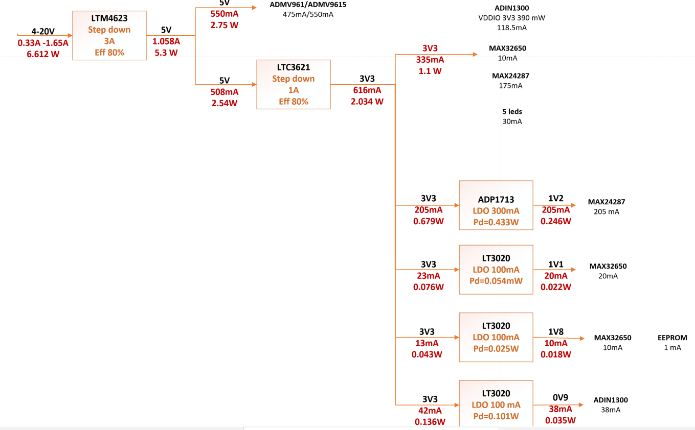
The main DC/DC regulator is the LTM4623, designed for 5V output. This will supply the ADMV96x5 and all the circuits on the ADMV96S-WGBE-EK1 board. The LTM4623 supports selectable discontinuous mode operation and output voltage tracking for supply rail sequencing. Its high switching frequency and current mode control enable a very fast transient response to line and load changes while providing very good stability.
The LTC3621 synchronous step-down regulator is the next in the power chain. The board uses the fixed version of this regulator but is also designed to be compatible with the adjustable version. The 3V3 rail is used to supply the PHY, MCU, and SerDes VDDIO, and is also used as an input for the ADP170 and LT3020 linear regulators that generate the lower voltage rails.
Status Indicators
Reference designator |
Function/Description |
|
|---|---|---|
DS1 |
Power on LED |
indicates the board has powered up and 5V is in range |
D3 |
TX LED |
red indicates; green indicates |
D4 |
RX LED |
red indicates; green indicates |
DS3 |
TX LOCK LED |
lock status of TX |
DS4 |
RX LOCK LED |
lock status of RX |
J1 |
left side LED |
status of ADIN1300 (blinks when there is activity on the link) |
J1 |
right side LED |
shows speed of the link: amber - 1 Gbps, green - 100 Mbps, off - 10 Mbps |