AD-GMSL716MIPI-EVK
GMSL2-to-MIPI Deserializer Board for SoC Camera Systems.
Overview
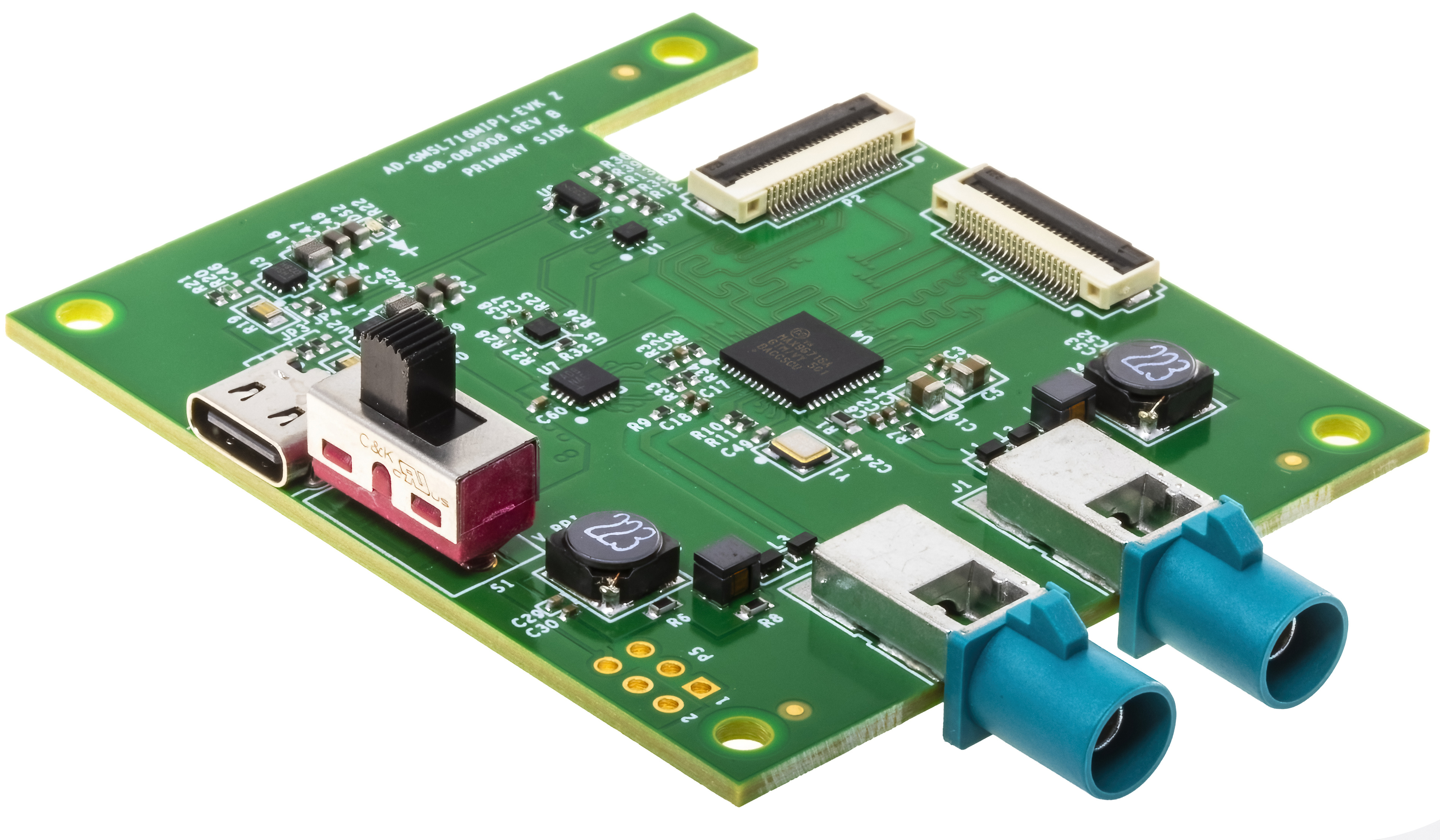
The AD-GMSL716MIPI-EVK is a compact, cost-effective GMSL2 deserializer evaluation board that bridges GMSL2 serialized video signals to MIPI CSI-2 interfaces for System-on-Chip platforms. Featuring the MAX96716A dual GMSL2 to CSI-2 deserializer, this board provides a robust solution for automotive and industrial vision applications.
The board addresses the market need for affordable GMSL camera solutions covering multiple sensor types. It implements Power over Coax functionality, allowing both data transmission and power delivery through a single coaxial cable, significantly simplifying system integration and cable management. The evaluation board includes comprehensive reference software with device tree and Linux images for all supported camera types.
Key technical capabilities include support for up to 15-meter cable lengths, 3Gbps or 6Gbps forward link rates, and bidirectional I2C communication for camera control. The board’s small form factor and mounting compatibility make it ideal for rapid prototyping and development of GMSL2 camera systems.
Features
Dual GMSL2 deserializer with MAX96716A
2 × MIPI CSI-2 22P (4 × lanes) ribbon cable connectors
2 × GMSL2 input connectors
Power over Coax implementation, 12V, 1.2A total output
Power input via USB-C 5V power input or via 6-pin connector
Compatible with NVIDIA Jetson, Raspberry Pi, and AMD SoC platforms
Individual MIPI CSI-2 connector
Small form-factor design for space-constrained applications
Mounting holes for secure attachment to Raspberry Pi
Applications
Advanced Driver Assistance Systems (ADAS)
Mobile and mounted robotics
Autonomous vehicles and automotive cameras
Outdoor machines and industrial equipment
Smart and flexible manufacturing systems
Security and surveillance systems
Industrial automation and machine vision
System Architecture
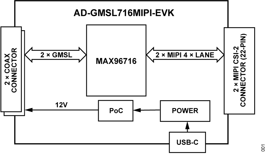
Forward Path (Camera to SoC):
Camera sensor captures image data
GMSL2 serializer converts parallel/MIPI data to GMSL2 serial stream
Data transmitted over coaxial cable at 3Gbps or 6Gbps
MAX96716A deserializer receives GMSL2 data
Data converted to MIPI CSI-2 format
MIPI CSI-2 output connects to SoC platform
Reverse Path (SoC to Camera):
Control commands originate from SoC platform
I2C/control signals processed by MAX96716A
Commands transmitted over GMSL2 reverse channel at 187.5 Mbps
Serializer receives and processes control commands
Commands applied to camera sensor and peripherals
Power Distribution:
5V input power received via USB-C connector or via the 6-pin connector
LTC3303 regulator converts 5V to required board voltages: 1.8V and 1.2V
PoC circuit using LT8337 generates 12V output for camera power
Power delivered to camera through coaxial cable
Specifications
Parameter |
Specification |
|---|---|
GMSL2 Inputs |
2 channels, 3Gbps/6Gbps configurable |
MIPI CSI-2 Outputs |
2 × 4-lane ports, up to 2.5 Gbps per lane |
Power Input |
USB-C or via the 6-pin connector, 5V ± 5% |
PoC Output |
12V, 1.2A total |
Cable Length |
Up to 15 meters |
Key Components |
MAX96716A, LTC3303 |
Package Contents
AD-GMSL716MIPI-EVK evaluation board
ESW-103-44-G-D 6POS dual row connector
2 x 05-22-D-0050-A-4-06-4-T FFC 22POS cable
8 x screws
4 x 21 mm standoffs
Hardware Components and Connections
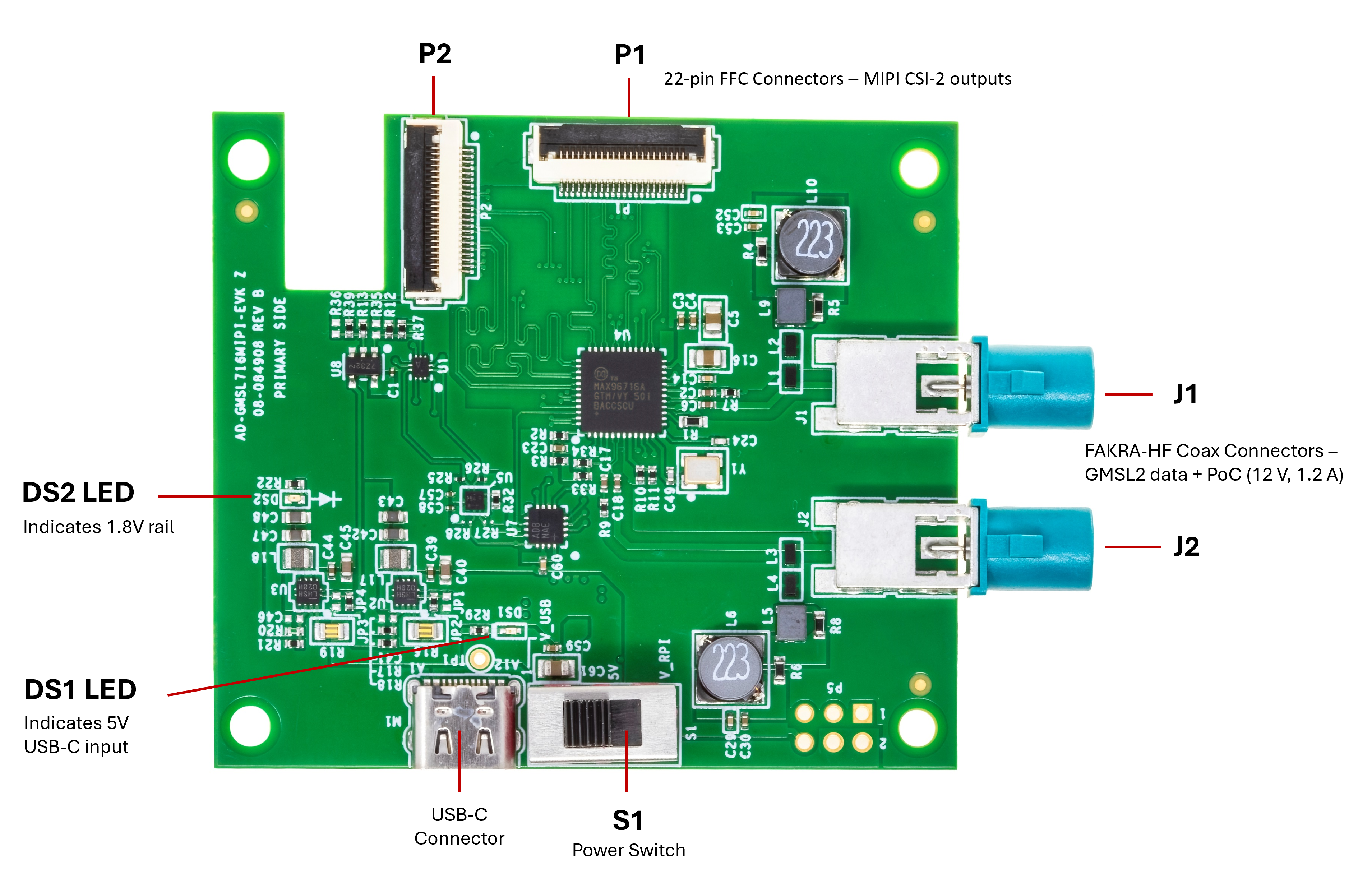
DS1 LED |
Indicates 5V USB-C input |
DS2 LED |
Indicates 1.8V rail |
P5 Connector |
Alternative 5V input and Raspberry Pi shield (same nets as Raspberry Pi’s GPIOs) |
S1 |
Power Switch / Up = USB-C power / Down = P5 power |
J1/J2 |
FAKRA-HF Coax Connectors – GMSL2 data + PoC (12V, 1.2A) |
P1/P2 |
22-pin FFC Connectors – MIPI CSI-2 outputs |
PoC Circuitry |
Delivers camera power over coax |
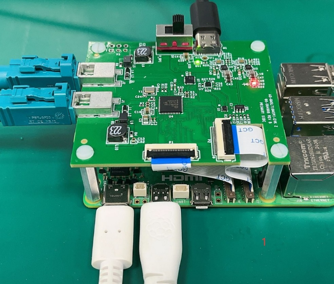
Hardware Setup
Equipment Needed
AD-GMSL716MIPI-EVK evaluation board
Compatible SoC development platform (Jetson, Raspberry Pi, AMD)
GMSL2 camera with serializer (for example, AD-GMSL717MIPI-EVK)
Coaxial cable (50Ω)
MIPI CSI-2 FFC/FPC cable (22-pin)
USB-C power supply (5V, minimum 2A)
Multimeter (for verification)
Power System Verification
Ensure all power sources are disconnected.
Verify USB-C power supply specifications (5V ± 5%).
Place the S1 power switch in the first (upper) position.
Connect a USB-C power cable to board.
GMSL2 Camera Connection
Connect GMSL2 camera to coaxial cable.
Verify cable specifications (50Ω coax).
Connect the coax cable to any of the GMSL connectors.
Ensure secure mechanical connection.
SoC Platform Connection
Select appropriate MIPI CSI-2 FPC cable.
Connect AD-GMSL716MIPI-EVK board MIPI output to SoC platform CSI-2 input.
Verify pin compatibility and orientation.
Secure cable connections.
Power-Up Sequence
Apply power via USB-C connector.
Verify LED illumination (via DS1/DS2 LED).
Check for GMSL2 link lock.
Monitor MIPI activity indicators.
Sample Measurements and Expected Readings
Supply voltage: 5.0V ± 0.25V at USB-C input
PoC output: 12.0V ± 0.5V, up to 1.2A
Link lock time: < 100ms typical
MIPI CSI-2 output levels: MIPI D-PHY v1.2 compliant
Resources
Software
The AD-GMSL716MIPI-EVK software package offers driver support and configuration tools for integrating GMSL2 cameras with popular SoCs, including device tree and kernel drivers.
Access the resources via the Analog Devices GMSL GitHub repository.
Design & Integration Files
Download
AD-GMSL716MIPI-EVK Design Support Package
Schematic
PCB Layout
Bill of Materials
Allegro Project
Help and Support
Analog Devices will provide limited online support for anyone using the reference design with Analog Devices components via the EngineerZone reference designs forum.
It should be noted that the older the tools’ versions and release branches are, the lower the chances to receive support from ADI engineers.