AD9695-FMC HDL project
Overview
The EVAL-AD9695 is a fully-featured evaluation board for the AD9695, a dual 14-bit, 1300/625MSPS analog-to-digital converter (ADC) featuring an on-chip buffer and a sample-and-hold circuit designed for low power, small size, and ease of use. The dual ADC cores feature a multistage, differential pipelined architecture with integrated output error correction logic. Each ADC features wide bandwidth inputs supporting a variety of user-selectable input ranges. The JESD204B links operate in subclass 1, with lane rates up to 16 Gbps.
The AD9695-FMC reference design is a processor-based embedded system. The design consists of a receive chain that transports the captured samples from the ADC to the system memory (DDR).
All cores from the receive chain are programmable through an AXI-Lite interface.
Supported boards
EVAL-AD9695 with 1300MSPS
For the 625MSPS variant, additional changes need to be done, which currently are not supported by our reference design.
Supported devices
AD9695 with 1300MSPS
Supported carriers
ZCU102 on FMC HPC1
Other required hardware
AD-SYNCHRONA14-EBZ as an external clock source
Block design
Block diagram
The data path and clock domains are depicted in the below diagram:
Clock scheme
Uses an external clock source: AD-SYNCHRONA14-EBZ
SYSREF clocks are LVDS
ADCCLK and REFCLK are LVPECL
Configuration modes
Note
AD9695 supports only JESD204B.
The following are the parameters of this project that can be configured:
RX_JESD_M: number of converters per link - by default set to 2
RX_JESD_L: number of lanes per link - by default set to 4
RX_JESD_S: number of samples per frame - by default set to 1
For more ways to configure this project, check Table 35 from the AD9695 data sheet, since in our design NP (or N’) is hardcoded to 16.
Keep in mind that the changes should be reflected in software as well. See Software related section for details.
Hardware considerations
The following connections should be made:
AD9695-FMC |
AD-SYNCHRONA14-EBZ |
|---|---|
J202 |
CH10_P |
J200 |
CH1_P |
P202 |
CH9_P |
ZCU102 |
AD-SYNCHRONA14-EBZ |
|---|---|
J79 |
CH2_P |
J80 |
CH2_N |
The jumper settings are the following, on AD9695-FMC:
Short P1, P304, P305, P307, P308, P309, P311, P312, P602 (SPI enable)
Short pins {3, 2} on P401 (the two towards the inside of the board)
DO NOT SHORT P100 (Power Down/Standby)
CPU/Memory interconnects addresses
The addresses are dependent on the architecture of the FPGA, having an offset added to the base address from HDL (see more at CPU/Memory interconnects addresses).
Instance |
ZynqMP |
|---|---|
rx_ad9695_tpl_core |
0x84A0_0000 |
axi_ad9695_rx_xcvr |
0x84A6_0000 |
axi_ad9695_rx_jesd |
0x84AA_0000 |
axi_ad9695_rx_dma |
0x9C40_0000 |
SPI connections
SPI type |
SPI manager instance |
SPI subordinate |
CS |
|---|---|---|---|
PS |
SPI 0 |
AD9695 |
0 |
PS |
SPI 1 |
PMOD |
0 |
GPIOs
GPIO signal |
Direction |
HDL GPIO EMIO |
Software GPIO |
Software GPIO |
|---|---|---|---|---|
(from FPGA view) |
Zynq-7000 |
Zynq MP |
||
fdb |
INOUT |
34 |
88 |
112 |
fda |
INOUT |
33 |
87 |
111 |
pwdn |
INOUT |
32 |
86 |
110 |
Interrupts
Below are the Programmable Logic interrupts used in this project.
Instance name |
HDL |
Linux ZynqMP |
Actual ZynqMP |
|---|---|---|---|
axi_ad9695_rx_dma |
13 |
109 |
141 |
axi_ad9695_rx_jesd |
12 |
108 |
140 |
Building the HDL project
The design is built upon ADI’s generic HDL reference design framework. ADI distributes the bit/elf files of these projects as part of the ADI Kuiper Linux. If you want to build the sources, ADI makes them available on the HDL repository. To get the source you must clone the HDL repository.
Examples on how to build the project:
Linux/Cygwin/WSL
Example for building with the default configuration:
~$
cd hdl/projects/ad9695_fmc/zcu102
~/hdl/projects/ad9695_fmc/zcu102$
make
Example for building with parameters:
~$
cd hdl/projects/ad9695_fmc/zcu102
~/hdl/projects/ad9695_fmc/zcu102$
make RX_JESD_M=2 RX_JESD_L=4
Default values of the make parameters for AD9695-FMC:
RX_JESD_M: 2
RX_JESD_L: 4
RX_JESD_S: 1
The result of the build, if parameters were used, will be in a folder named by the configuration used.
If the following command was run
make RX_JESD_L=4
then the folder name will be RXL4.
Check Configuration modes for more details.
A more comprehensive build guide can be found in the Build an HDL project user guide.
Software considerations
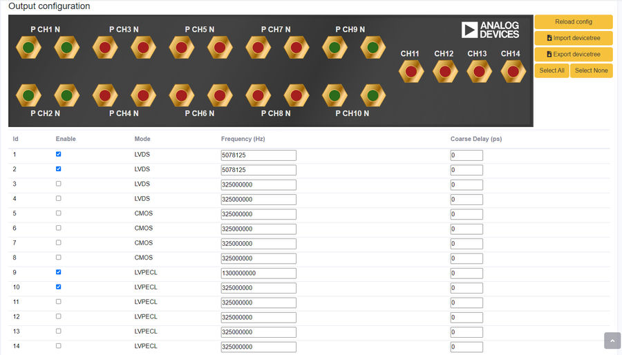
AD-SYNCHRONA14-EBZ output configuration:
Only the channels presented in the clocking selection are relevant. For the rest, you can either disable them or just put a divided frequency of the source clock.

More details on how to set up the AD-SYNCHRONA14-EBZ can be found on its wiki page.
Resources
More information
Support
Analog Devices, Inc. will provide limited online support for anyone using the reference design with ADI components via the EngineerZone FPGA reference designs forum.
For questions regarding the ADI Linux device drivers, device trees, etc. from our Linux GitHub repository, the team will offer support on the EngineerZone Linux software drivers forum.
For questions concerning the ADI No-OS drivers, from our No-OS GitHub repository, the team will offer support on the EngineerZone microcontroller No-OS drivers forum.
It should be noted, that the older the tools’ versions and release branches are, the lower the chances to receive support from ADI engineers.