Troubleshooting JESD204B TX links
Running one of the below commands on a Linux-based system will return the status of the JESD link. This is one of the firsts steps to diagnose the link.
~$
jesd_status
or running the following command:
~$
grep "" /sys/bus/platform/devices/*.axi-jesd*/status*
Link is enabled
Measured Link Clock: 184.320 MHz
Reported Link Clock: 184.320 MHz
Lane rate: 7372.800 MHz
Lane rate / 40: 184.320 MHz
LMFC rate: 11.520 MHz
SYNC~: deasserted
Link status: DATA
SYSREF captured: Yes
SYSREF alignment error: No
Common symptoms
Below are the most commonly-occurred problems during link bring-up, and solutions to overcome these in a Linux environment.
Missing JESD link layer peripheral, *.axi-jesd*/status*: No such file or directory
Cause: Base address mismatch between HDL and device tree, the drivers for “adi,axi-jesd204-tx-1.0” or “adi,axi-adxcvr-1.0” do not probe.
Identify: Check address allocation in the block design or in system_bd.tcl, against the corresponding device tree Physical and Link layer nodes.
Fix: Adjust addresses. For ZCU102, add 0x2000_0000 offset to the address used in HDL. Check CPU/Memory interconnects addresses section for details for other carriers.
Link is DISABLED, In Linux boot log following appears: axi-adxcvr-tx: TX Error: 0
For this, there could be at least 3 causes, listed below.
Cause 1: QPLL or CLL does not lock due missing reference clock.
Identify: Check reference clock location constraints. Check if the clock reaches the quads that are used.
Fix: Adjust location constraints.
Or:
Cause 2: QPLL or CLL does not lock due incorrect synthesis parameters.
Identify: Check channel and common util_adxcvr parameters against ones created with the transceiver wizard.
Fix: Adjust the synthesis parameters of the util_adxcvr component.
Or:
Cause 3: QPLL or CLL does not lock due frequency mismatch of reference clock. Reference clock frequency is not the one the CPLL or QPLL was set to handle forcing the VCO go out of range.
Identify: Check reference clock generation settings.
Fix: Adjust setting of the clock chip to generate the correct frequency.
Link is DISABLED, in Linux boot log following appears: axi-jesd204-tx 44b90000.axi-jesd204-tx: axi_jesd204_tx_jesd204_link_setup: Link0 set lane rate 16500000 kHz failed (-22) …
Cause: QPLL can’t find a configuration for desired lane rate with the given reference clock.
Identify: Check boot log. Check the required lane rate — reference clock combination against the constraints defined in the transceiver manual.
Fix: Configure the clock chip for a different reference clock, or switch to CPLL or QPLL0/1.
Link is DISABLED, In Linux boot log following appears: axi-adxcvr-tx: QPLL: failed to find setting for lane rate …
Cause: QPLL can’t find a configuration for desired lane rate with the given reference clock.
Identify: Check boot log. Check the required lane rate — reference clock combination against the constraints defined in the transceiver manual.
Fix: Configure the clock chip for different reference clock, or switch to CPLL.
Link status stays in CGS and SYNC~ stays asserted
Cause 1: SYNC~ signal does not reach Link layer HDL component.
Identify: Check location constraints against schematic.
Fix: Adjust location constraints to match the schematic.
Cause 2: SYNC~ signal polarity reversed.
Identify: Check constraints and schematic; look for any polarity inversion.
Fix: Adjust location constraints to match the schematic.
Cause 3: JESD RX can’t detect the CGS characters due different lane rate settings.
Identify:
Check if “Measured Link Clock” matches “Reported Link Clock” and “Lane Rate/40”.
Check if Lane Rate is as expected
If OUTDIV_CLK is used for link clock, adjust “out-clk-select” to match
Lane Rate/40.If dedicated link clock is used, adjust the external clock chip from device tree to output a clock of
Lane Rate/40.
Fix: See this important note
Link status stays in CGS and SYNC~ is deasserted
Cause 1: SYNC~ signal not connected correctly, pulled high
Identify: run
jesd_statusorgrep "" /sys/bus/platform/devices/*.axi-jesd*/status*Link status: CGS SYNC~: deasserted
Fix: Make sure SYNC~ is connected to the Link Transmit peripheral and is properly driven.
Cause 2: Receive endpoint of the JESD link is not up
Identify:
jesd_statusorgrep "" /sys/bus/platform/devices/*.axi-jesd*/status*Link status: CGS SYNC~: deasserted
Fix: Make sure software communicates correctly with the DAC, bring-up sequence was executed and JESD RX blocks configured and enabled.
Cause 3: Missing SYSREF at peripheral in subclass 1
Identify:
jesd_statusorgrep "" /sys/bus/platform/devices/*.axi-jesd*/status*Link status: CGS SYNC~: deasserted SYSREF captured No
Fix: Make sure SYSREF is connected to the Link Transmit peripheral and is properly driven.
Link status stays in DATA but output tone not as expected, raised noise floor
Cause: Lane polarity inversion.
Identify: Read received ILAS registers from DAC, in such case they do not make any sense compared to the LANEn_ILAS0..3 registers of the axi_jesd204_tx. ILAS checksum mismatch.
Fix: For each in use lane adjust the corresponding bit in the TX_LANE_INVERT parameter of the util_adxcvr component to match any polarity inversion from the schematic.
Link status stays in DATA but output not as expected
E.g.: For a Link Clock: 184.320 MHz; Nothing is transmitted from the Transport layer, but spectrum looks like below:
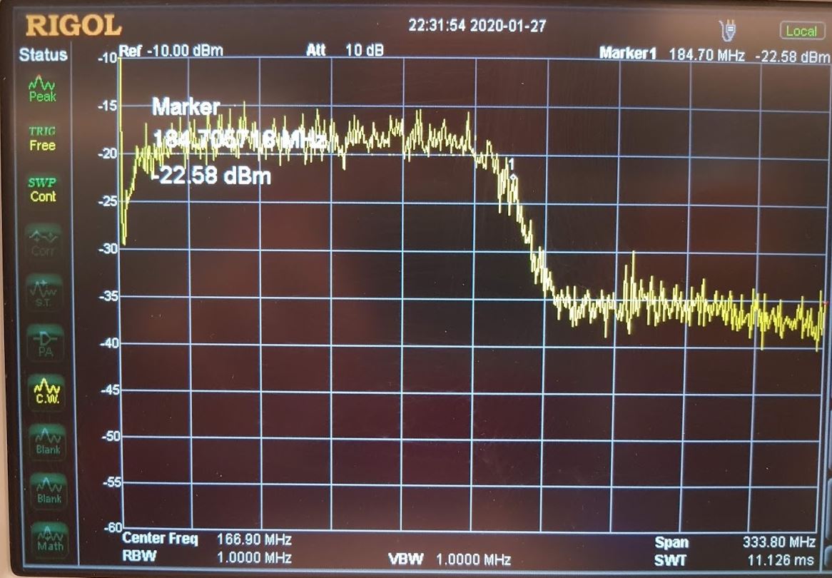
Cause: Mismatch in scrambling configuration.
Identify: Check scrambling configuration registers from DAC against LINK_CONF1 config register SCRAMBLER_DISABLE bit of the Link transmit peripheral.
Fix: Adjust the above bits to match configuration.
Link status stays in DATA but output tone not as expected
Cause: Swapped lanes, source ‘Lane n’ connects to other than sink ‘Lane n’;
Identify: Read received LID in the ILAS registers of the DAC, in such case they are out of order, permuted.
Fix: Adjust link layer to physical layer connections in the FPGA block design through ad_xcvrcon procedure lane_map parameter; or adjust crossbar from the DAC through the device tree nodes.
Link status stays in DATA but output tone not as expected, signal and its spectrum presents randomness
Cause: Incorrect or missing constraint of the device clock (Lane Rate/40)
Identify: Report clocks of the transport layer, link layer component.
Fix: In the constraints file define/create clocks with period that match desired Lane Rate/40.
SYSREF alignment error: Yes
Cause 1: Frequency of SYSREF signal is not as expected.
Identify: Check SYSREF generator parameters.
Fix: Set the frequency of SYSREF to be an integer submultiple of the reported local multiframe clock (LMFC), implicitly not bigger than LMFC (<= LMFC).
Cause 2: SYSREF signal sampling does not meet setup/hold requirements.
Identify: Check if SYSREF path is constrained.
Fix: Define timing constraints for SYSREF in edge-aligned source-synchronous interface mode and adjust device clock and SYSREF phase from the clock chip accordingly.