
AD5706R HDL project
Overview
The AD5706R devices are 4-channel, 16-/12-/10-bit resolution, low noise, programmable current output, digital-to-analog converter (DAC) capable of multiple operating modes and output current ranges with high power efficiency. These are intended for photonics control and current mode biasing applications. The devices incorporate a 2.5V, on-chip voltage reference, die temperature, load DAC, and A/B toggle functions, output monitoring functions, and reset functions.
The family provides multiple programmable output current ranges up to 300mA. With device addressable pins, an SPI transaction can communicate with up to four AD5706R on the same SPI bus. Each DAC operates with an independent positive power supply rails PVDDx from 1.65V to 3.6V, for optimizing power efficiency and thermal power dissipation. The AD5706R operate from a 2.9V to 3.6V AVDD supply and are specified over the −40°C to +125°C temperature range.
Applications:
Photonics Control
Optical Communications
LED Driver Programmable Current Source
Current Mode Biasing
Supported boards
Supported devices
Supported carriers
Cora Z7-07S on Arduino Header
Block design
Block diagram
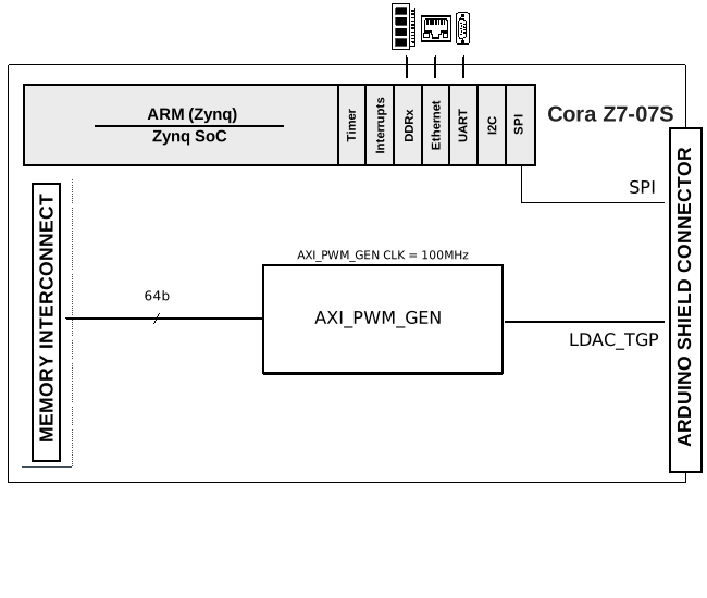
The data path is depicted in the below diagram:
Hardware setup
Signal |
AD5706R Testpoint |
Cora Z7s |
|---|---|---|
SPI_CSB |
CS |
CHIPKIT IO 10 |
SPI_SDO |
SDO |
CHIPKIT IO 11 |
SPI_SDI |
SDI |
CHIPKIT IO 12 |
SPI_SCLK |
SCK |
CHIPKIT IO 13 |
SHDN |
PMOD P7 |
CHIPKIT IO 7 |
RESETB |
RESET |
CHIPKIT IO 8 |
LDACB_TGP |
PMOD P6 |
CHIPKIT IO 9 |
Important
The evaluation board is powered by 5 V voltage from an external USB.
CPU/Memory interconnects addresses
The addresses are dependent on the architecture of the FPGA, having an offset added to the base address from HDL (see more at CPU/Memory interconnects addresses).
Instance |
Zynq |
|---|---|
axi_ad5706R_pwm_gen |
0x44A00000 |
xadc_in |
0x44A50000 |
GPIOs
The Software GPIO number is calculated as follows:
Zynq-7000: if PS7 is used, then the offset is 54
GPIO signal |
Direction |
HDL GPIO EMIO |
Software GPIO |
|---|---|---|---|
(from FPGA view) |
Zynq-7000 |
||
RESETB |
OUT |
32 |
86 |
SHDN |
OUT |
33 |
87 |
Building the HDL project
The design is built upon ADI’s generic HDL reference design framework. ADI distributes the bit/elf files of these projects as part of the Kuiper. If you want to build the sources, ADI makes them available on the HDL repository. To get the source you must clone the HDL repository, and then build the project as follows:
Linux/Cygwin/WSL
~$
cd hdl/projects/ad5706r/coraz7s
~/hdl/projects/ad5706r/coraz7s$
make
A more comprehensive build guide can be found in the Build an HDL project user guide.
Resources
More information
Support
Analog Devices, Inc. will provide limited online support for anyone using the reference design with ADI components via the EngineerZone FPGA reference designs forum.
For questions regarding the ADI Linux device drivers, device trees, etc. from our Linux GitHub repository, the team will offer support on the EngineerZone Linux software drivers forum.
For questions concerning the ADI No-OS drivers, from our No-OS GitHub repository, the team will offer support on the EngineerZone microcontroller No-OS drivers forum.
It should be noted, that the older the tools’ versions and release branches are, the lower the chances to receive support from ADI engineers.