AD-FMCOMMS3-EBZ Specifications
Transmit and Receive Specs
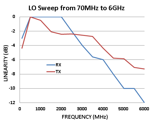
LO BW
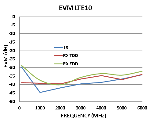
EVM
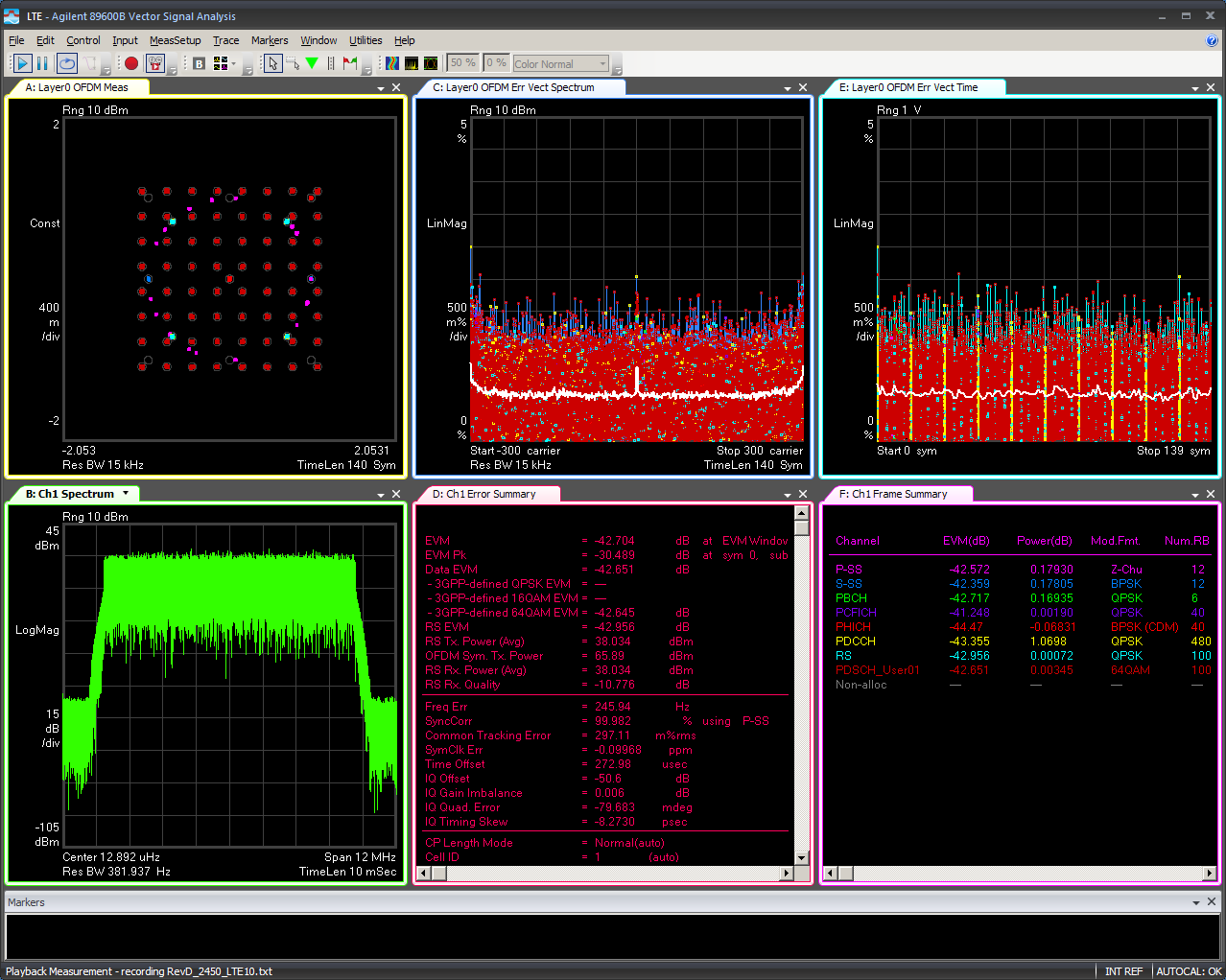
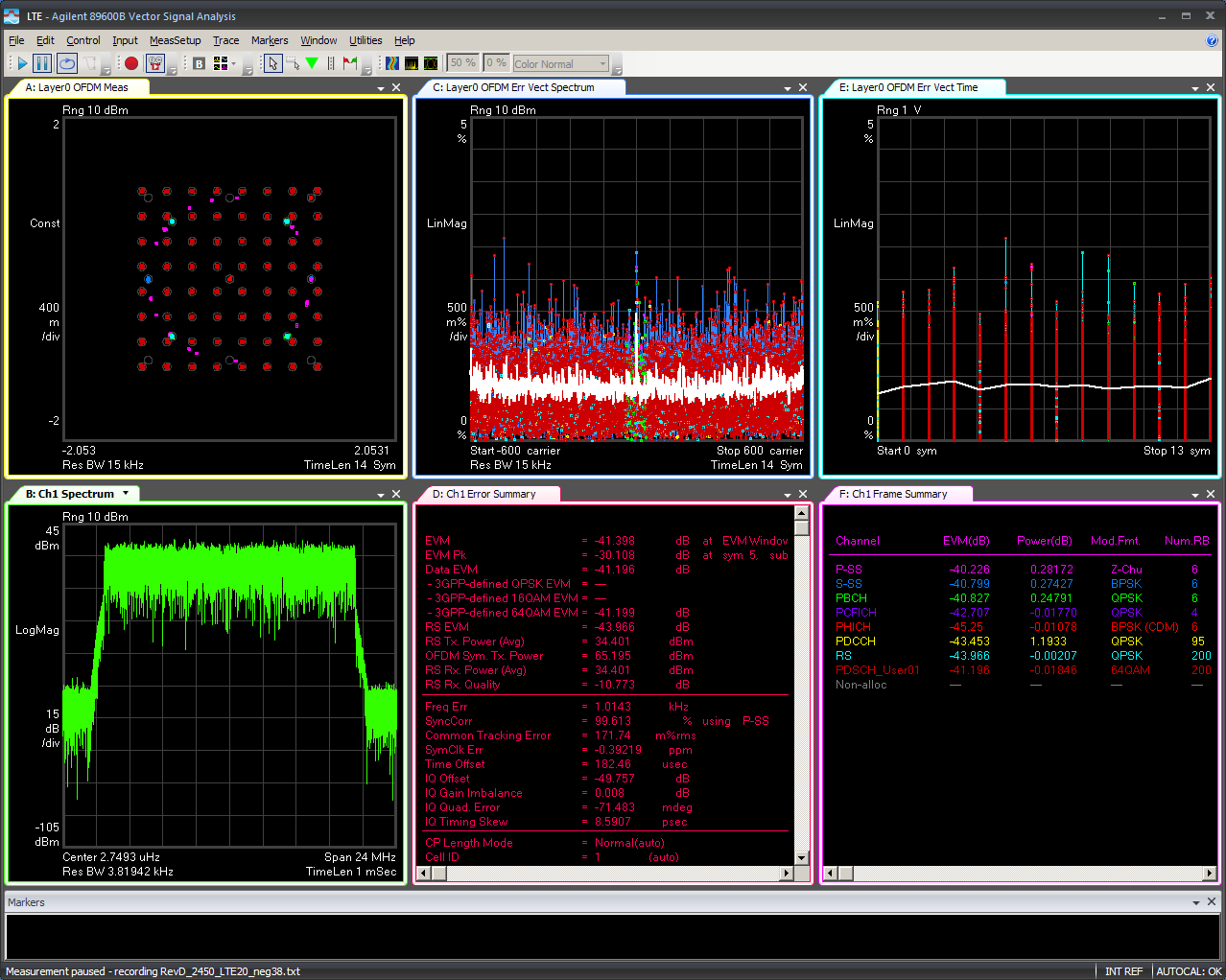
The error vector magnitude or EVM (sometimes also called receive constellation error or RCE) is a measure used to quantify the performance of a digital radio transmitter or receiver.
A signal would normally be sent by an transmitter and then received by a receiver, and the resulting constellation would be precisely compared to the ideal constellation location. This is a interesting metric since any sort of imperfections in either the transmit or receive implementation (such as carrier leakage, image rejection, phase noise, group delay mismatch, any nonlinearity, jitter, timing recovery, equalization, etc) will cause the actual constellation points to deviate from the ideal locations.
Since EVM is a total system test, users must understand for testing a receiver, a transmitter with better performance that the receiver is required. For testing a transmitter, a receiver with better performance than then transmitter is required. Care must be taking to understand the “weakest” link, and where the performance limit is coming from. It can be any of:
transmitter
receiver
receive algorithm
In many cases
LTE is
used for EVM testing, since it such as well defined, and understood
standard for high-speed wireless communication for mobile phones and
data terminals. The
European Telecommunications Standards Institute
(ETSI) has detailed standards
which define the waveforms used for LTE EVM testing, including:
EVM of single 64QAM PRB (for 1.4 MHz, 3 MHz, 5 MHz, 10 MHz, 15 MHz, and 20 MHz channels) at max and min powers
EVM for 16QAM modulation (for 1.4 MHz, 3 MHz, 5 MHz, 10 MHz, 15 MHz, and 20 MHz channels)
EVM for QPSK modulation (for 1.4 MHz, 3 MHz, 5 MHz, 10 MHz, 15 MHz, and 20 MHz channels)
To create these vectors to play out either a bench instrument, or a SDR platform, most people (including ADI) use one of:
Keysight SignalStudio
MathWorks LTE System Toolbox
On the receive side (to actually decode the LTE signal, and measure EVM), we use one of:
Keysight 89600 VSA Software
MathWorks LTE System Toolbox
To complicate matters, EVM is a unit-less measurement. It’s a ratio, which can be represented in both percent (%) or as a dB (converting to log scale). Since dB will show you in details where the differences are - it’s easier to understand the difference between 2%, 1% and half a percent by discussing -34 dB, -40 dB, -46 dB (which are the same physical error). Typically EVM performance of less than -35 dB is required for many communications applications.
Transmit Specs
Tx Output Power vs Frequency
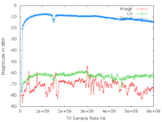
Since there is a large (2 orders of magnitude) tuning range of the device (70 MHz to 6000 MHz), it’s good to understand how much power the AD9361 can output.
Tests were done both with CW (single tone 10 MHz offset from the LO), measuring output power, lo leakage, and image.
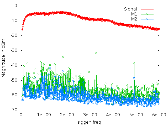
Tests should also be done with a wide band signal (LTE 10), measuring output power, and ACPR.
Adjacent Channel Power
Phase Noise
Output power
Intermodulation Distortion
Bandwidth
Receive Specs
Signal to Noise
Noise floor
Input sensitivity
Dynamic range
LO BW
EVM