Profile generation flow using TES
Profiles
ADRV9002 uses profiles to designate different device configuration
settings for the Tx/Rx channels. The profile dictates how the digital
filters, analog filters, clock rates, and clock dividers are configured
in the device. Some specific parameters set by profiles include the IQ
data rate, ADC clock rate, analog filter corners, FIR filter
coefficients, and interpolation/decimation factors in the half-band
filters. Several profiles can be examined in the ADRV9002 Transceiver
Evaluation Software for given device clock frequencies. If the desired
profile exists in the software, it is recommended to set up the desired
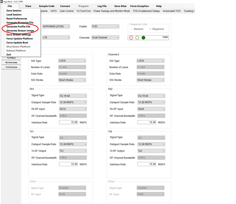
profile in and use the generated JSON file by pressing the
Generate Profile File button. Custom profiles can be generated using
other ADI software tools not described here
ADRV9002 transceiver evaluation software (TES)
.
Warning
Profiles are specific to the versions of ADRV9001/2 API that the driver uses. Therefore, they must be generated from the TES software that coincides with that API version. Unfortunately, profiles themselves are not versioned so it is recommended to note the API version in the generated profile filenames when created. The driver will print the API version during boot for reference.
For more information about profiles and how to load please see here: ADRV9002
Note
We are about to release a library which allows device profile generation outside of TES. This library can be used in applications such as the IIO Oscilloscope, or other SDR software.
Installation and Configuration
Detailed installation and configuration instructions can be found under
section TRANSCEIVER EVALUATION SOFTWARE (TES) in the
UG-1828:ADRV9001 system development user guide
Download:
Worked example
In the following picture we can see the base controls for the profile:
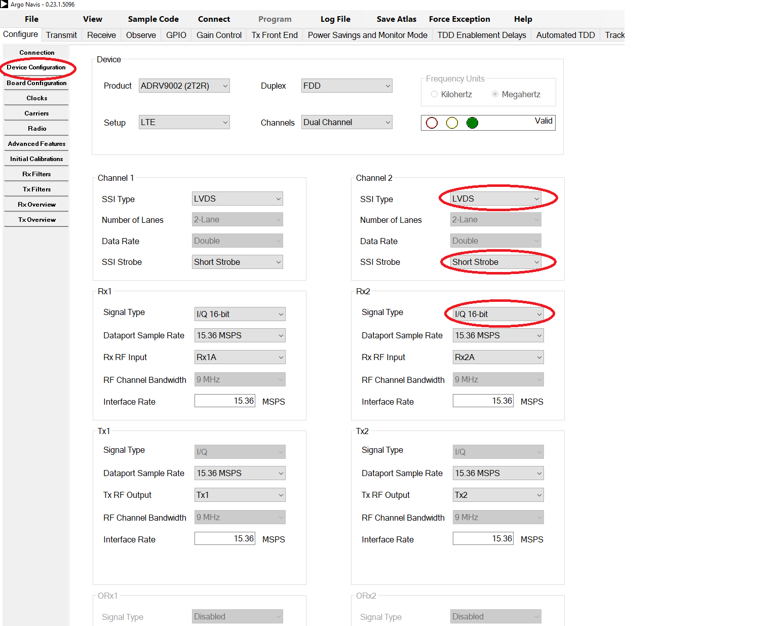
In here, one can change the main profile type (LTE, DMR, etc), interface rate, disabling ports and so on…
Caution
Special care for the fields highlighted in channel 2 (also applies for channel 1) that must be set like in the image. The LVDS enforcement is specific to jupiter.
Once we are done with the settings, time to generate the stream and the profiles files:
In the next subsections, we can see some extra and useful settings that one might want to set before generating the stream and the profile files.
Enable NCO Frequency offset
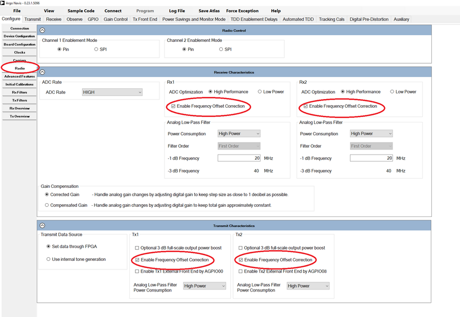
Note
Enabling this setting, enables the IIO attribute ADRV9002. These settings are on by default on jupiter default profile.
Enable Antenna Diversity
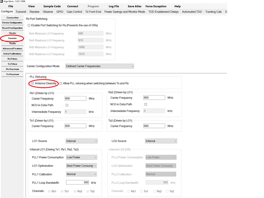
Note
This setting affects the LO mapping (which ports each LO drives). Basically having this on, means that all ports are mapped into the same LO.
Warning
This settings is obviously only available if TDD is set in the Device Configuration tab
Enable Frequency hopping
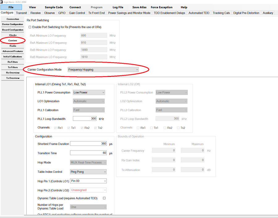
Note
The only thing needed to do in TES is just to enable Frequency hopping as highlighted. All the other settings does not map in any profile setting…