Jupiter_SDR MCS Setup
Hardware requirements

1x Main machine running Linux - it’s goal is to control and process data from others, through Ethernet(ssh)
2x jupiter_sdr + USB C Power supply (5V/3A, 9V/3A) if PoE is not available.
2x SD card(min 32G) for jupiter_sdr
1x Synchrona + ADD-ON Voltage Translation Board + 12V Power Supply
1x Ethernet Switch/Router
3x Ethernet cables
3x Micro-USB (UART)
9x SMA cables
4x SMA cables of same length and type for > 6GHz (splitter to Jupiter_sdr Rx)
4x SMA cables for of same length and type for > 6GHz (synchrona to jupiter)
1x SMA cable (Jupiter_sdr Tx to splitter input)
Important
We chose to use Synchrona for clock and MCS requests. If you have a different sync setup the constraints are:
Clocks, MCS 6 pulse train or MCS requests should be generated from the same source for both systems
2x 30.72 MHz, (LVPECL)
2x MCS pulse, at request (LVPECL)
The trace length should be equal for all mcs and clock paths, from reference to the systems inputs. This is if you can afford to delay the MCS in regard to the clock, otherwise the MCS cables should be longer than the clock ones.
MCS prebuild files
Jupiter SDR boot partition files for MCS sync example:
Device tree source and blob overlay for Synchrona:
Caution
There is a known issue with this Image version that the IP of the board will change from boot to boot because the MAC addr is not read from the flash memory on the Jupiter
Setup
Write the latest Kuiper image on the SD cards Kuiper images
Copy on the boot partition of the SD cards, the provided boot files from the archive above, for MCS sync (Image, system.dtb, BOOT.BIN and boot.scr)
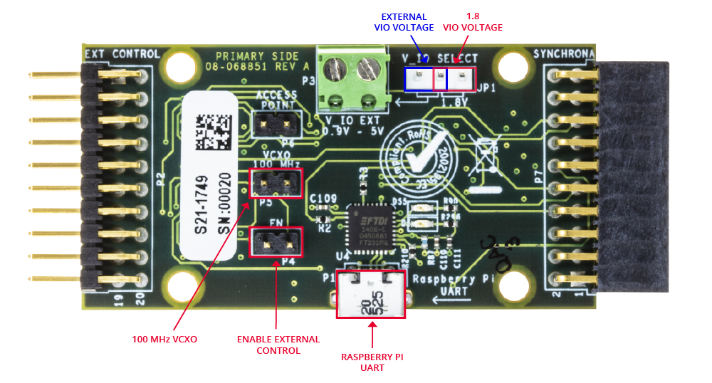
Configure the Synchrona, see the Jupiter_SDR MCS Setup.
Connect all SMA cable and terminations as described in connecting_jupiter_sdr_with_synchrona section
The reference clock from the signal generator(Synchrona) must be, connected, and running before the next step
Insert the SD cards and power up the jupiter_sdrs
You need all 4 machines(Main, jupiter_sdr, Synchrona) in the same LAN network, even if a DHCP server is not present
Using a UART terminal, read the IP addresses of the Jupiter_SDRs and Synchrona. By entering “ifconfig” in their UART console
On the main Linux machine, make sure you have installed python3, libiio and pyadi-iio more info in prepare_and_run_python_tests section.
Enter in the folder examples/adrv9002_mcs_sync and run “python3 jupiter_sync.py”.
Setting Synchrona for MCS setup
Power up the system/Wait for it to boot(1min).
Using a UART terminal, read the IP address of the Pi(synchrona). Enter ifconfig
Copy the device-tree rpi-ad9545-hmc7044.dtbo on the synchrona SD card via scp (or locally on a different machine) on the boot partition in /boot/overlays. Loading the devicetree object in the GUI might get the desired frequency but it will not wait for a synq request.
Reboot Synchrona
To check if the configuration was set, after reboot, you can enter in a browser enter the IP address. In the GUI that will open in browser, log in with User ”admin”, pass: “analog”
If your Synchrona does not boot or you need a fresh SD card for synchrona, you should re-image the SD card with the image from the bottom of this section, or check if there is a newer version on ad-synchrona14-ebz
Write the image to an SD card, 16 G or above. Using your favourite tool
Insert the freshly written SD card into the Synchrona’s raspberry Pi and power up the system
After boot, configure the following in the serial terminal:
Make sure in the /boot/config.txt there the below line pointing to the Synchrona devicetree overlay.
dtoverlay=rpi-ad9545-hmc7044.dtbo
By default, the IP is static. 192.168… . So, if needed you can enable the dhcp by running the enable_dhcp.sh script:
root@analog:~# cd /root/linux_image_ADI-scripts/
root@analog:/linux_image_ADI-scripts# ./enable_dhcp.sh
root@analog:/linux_image_ADI-scripts# reboot
After reboot, start from setting_synchrona_for_mcs_setup point 1. above.
More info on ad-synchrona14-ebz
None of the jumpers should be connected on Synchrona’s ADD-ON board
Download
22 June 2022 release
Connecting Jupiter SDR with Synchrona
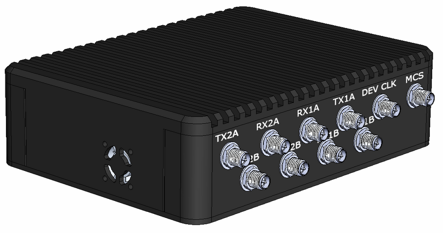
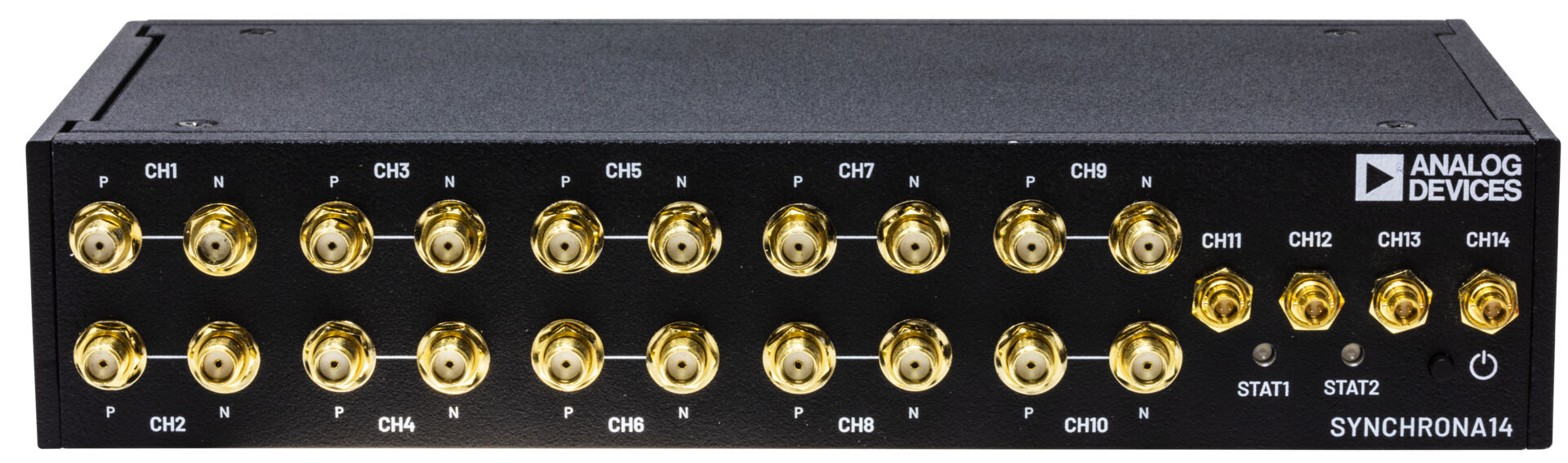
Synchrona SMA |
Jupiter SMA |
Signal |
Frequency |
Standard |
|---|---|---|---|---|
ch9_p |
Ref Clk |
Clock |
30.72 MHz |
LVPECL |
ch10_p |
Ref Clk |
Clock |
30.72 MHz |
LVPECL |
ch5_p |
MCS |
MCS |
640 KHz |
CMOS |
ch8_p |
MCS |
MCS |
640 KHz |
CMOS |
Caution
ch9_n and ch10_n must have 50 ohm SMA terminations.

Configuring Synchrona in a 4 Jupiter SDR syncronization setup
Not all channels can be used, some channels have the option for sync request, others don’t. Below is a table with the possible sync scheme, sine channels require soldering components on Synchrona. More info on ad-synchrona14-ebz
Synchrona SMA |
Jupiter SMA |
Signal |
Frequency |
Standard |
|---|---|---|---|---|
ch1_p |
MCS |
MCS |
640 KHz |
CMOS |
ch2_p |
Ref Clk |
Clock |
30.72 MHz |
LVPECL |
ch3_p |
Ref Clk |
Clock |
30.72 MHz |
LVPECL |
ch4_p |
MCS |
MCS |
640 KHz |
CMOS |
ch5_p |
MCS |
MCS |
640 KHz |
CMOS |
ch6_p |
Ref Clk |
30.72 MHz |
||
ch7_p |
Ref Clk |
30.72 MHz |
||
ch8 |
MCS |
MCS |
640 KHz |
CMOS |
ch9_p |
Ref Clk |
Clock |
30.72 MHz |
LVPECL |
ch10_p |
Ref Clk |
Clock |
30.72 MHz |
LVPECL |
Caution
Each negative pair of a clock must have 50 ohm SMA termination mounted.
Prepare and run Python tests
We recommend that you have git installed on your machine. Because we need a specific branch of the development repo.
sudo apt install git
You also need to have libiio and pyadi-iio installes, as described below Install the required tools
sudo apt-get update
sudo apt install git
sudo apt-get install build-essential
sudo apt-get install libxml2-dev libzstd-dev bison flex libcdk5-dev cmake
sudo apt-get install libaio-dev libusb-1.0-0-dev
sudo apt-get install libserialport-dev libavahi-client-dev
sudo apt-get install doxygen graphviz
sudo apt-get install python3 python3-pip python3-setuptools
apt install python3.10-venv
pip install paramiko
pip install matplotlib
Clone libiio, use v0.25.
git clone https://github.com/analogdevicesinc/libiio.git
git checkout  v0.25
cd libiio
mkdir build
cd build
cmake ../ -DCPP_BINDINGS=ON -DPYTHON_BINDINGS=ON
make -j$(nproc)
sudo make install
cd ../..
Clone and install pyadi-iio, use tfcollins/jupiter-sync brnach. The below example was runed on Ubuntu 22.4, which requires a virtual environment.
git clone https://github.com/analogdevicesinc/pyadi-iio.git
cd pyadi-iio
git checkout tfcollins/jupiter-sync
python3 -m venv venv
sudo apt install python3.10-venv
source venv/bin/activate
pip install -e .
Go to the example jupiter scripts folder and edit, using your desired editor, jupiter_sync.py. Add the ip addr of the Synchrona and of the Jupiters to sync.
cd examples/adrv9002_mcs_sync
vim jupiter_sync.py
The script can synchronize from 1 up to 4 Jupiters. At this moment, the limit comes from Synchrona’s available outputs.
synchrona_ip = "192.168.0.1"
device_ips = ["192.168.0.2", "192.168.0.3", "192.168.0.4", "192.168.0.5"]
Call the script
python3 ./jupiter_sync.py
Expected results
DEBUG:adi.adrv9002_multi:Creating primary device: ip:192.168.0.2
DEBUG:adi.adrv9002_multi:Creating secondary device: ip:192.168.0.3
DEBUG:adi.adrv9002_multi:Creating secondary device: ip:192.168.0.4
DEBUG:adi.adrv9002_multi:Creating secondary device: ip:192.168.0.5
Loading profiles
DEBUG:adi.adrv9002_multi:Setting profile_config on ip:192.168.0.2
DEBUG:adi.adrv9002_multi:Setting profile_config on ip:192.168.0.3
DEBUG:adi.adrv9002_multi:Setting profile_config on ip:192.168.0.4
DEBUG:adi.adrv9002_multi:Setting profile_config on ip:192.168.0.5

Waiting for 6 pulses
Requesting sysref
Waiting for MCS done on ip:192.168.0.2
ARM rx DMA and DDS cores
Mute DAC data sources
ARM RX/TX transfer paths
Configure DDSs
Set DDS as DAC data source
Enable Rx channels and define buffer size
Issue Sync pulse
Capture data
A window with a python plot will appear.
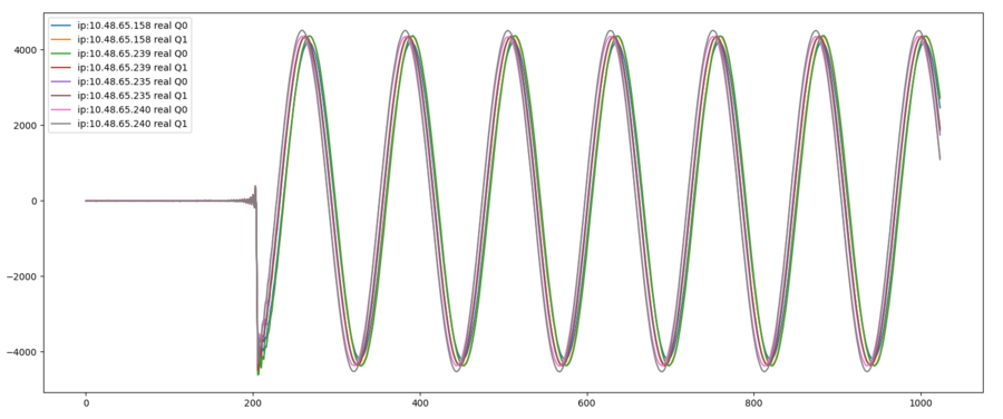
Description of key aspects
MCS process
jupiter_sdr signal chain description
The clock and MCS requests, generated by Synchrona, are driving the Jupiter_SDRs. The 6 MCS pulses required by adrv9002, are generated in HDL and have characteristics defined in software by the user.
The MCS procedure is not enough to synchronize the systems.
After MCS we will have synchronized clocks and LOs. Each Rx channel has in independent SSI reference clock driving the data path up to a DMA. Meaning, for this e.g. to synchronize a reception, we have to synchronize 4 DMAs across 2 systems. This is done with a sync_req from Synchrona. The sync_request will generate a trigger pulse in the HDL MCS sync logic, dedicated for the transmission steps. Which will release the armed Rx DMAS on the start_sync DMA feature/signal.
The Tx receives the same trigger signal, which releases the cores from the armed state.
Notes
SSI - source synchronous interface
MCS - Multi Chip Synchronization
Tips
If you can connect the systems to a LAN which has DHCP server, it is recommended to do so. Otherwise, you can use a switch and set static IPs.
If you get a static IP and are expecting one from your network, call script:
./enable_dhcp.sh
Same for Jupiter and Synchrona, see Synchrona setup above.
If you need a static IP, you can set the system for a desired IP by calling:
enable_static_ip.sh 192.168.1.100 eth0
Resources
Branches:
Jupiter SDR boot partition files for MCS sync example:
Device tree source and blob overlay for Synchrona: