EVAL-CN0556-EBZ
Programmable High Current and Voltage Source/Sink Power Supply.
Overview
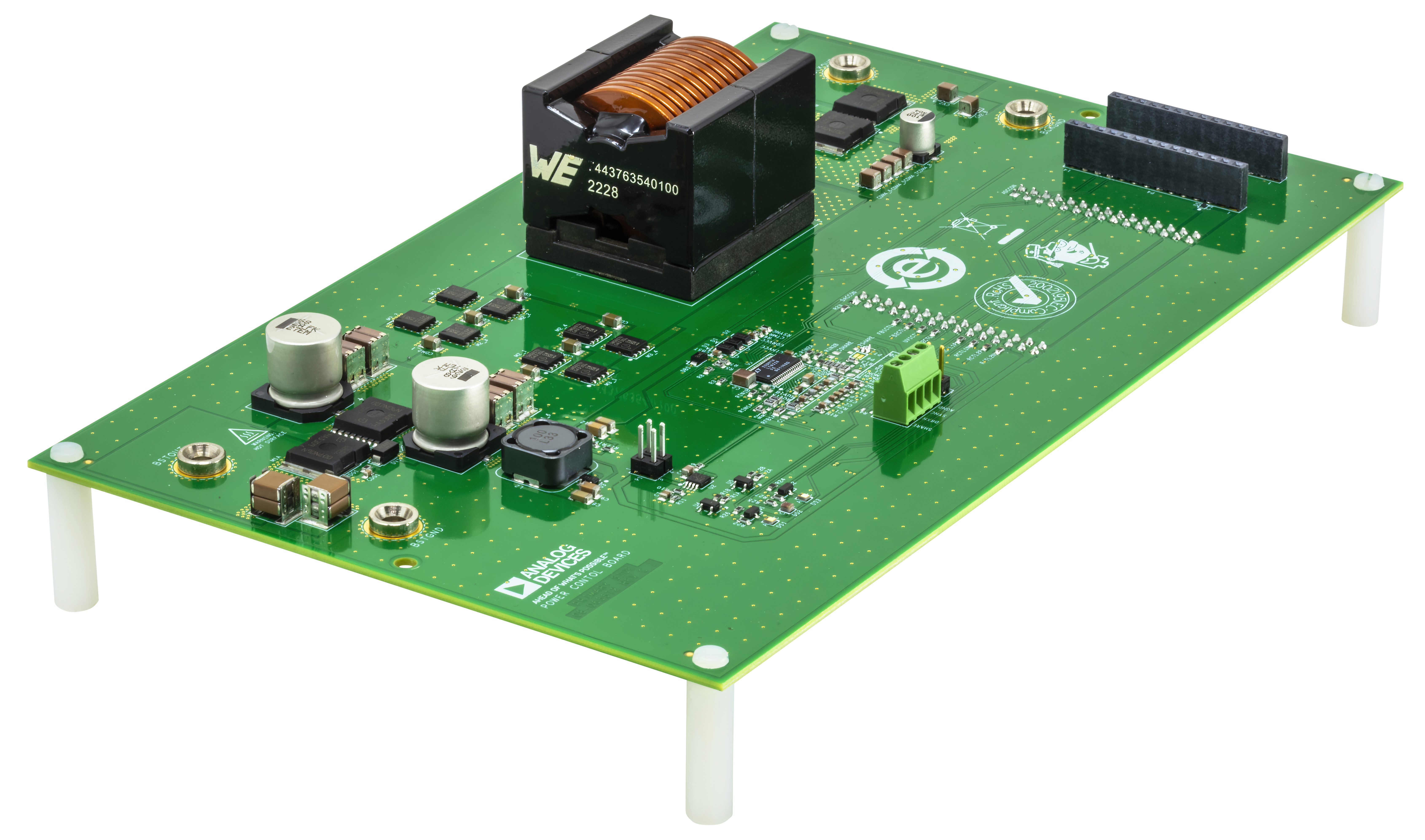
The EVAL-CN0556-EBZ is a programmable buck or boost power supply featuring an adjustable buck output of 2V to 14V, 35A, and adjustable boost output of 14V to 56V, 10A. The design allows the mode of operation to externally controlled or automatically selected. Six independent control loops regulate input and output voltage in both directions, as well as provide input and output current limit programming and monitoring.
The system input and output voltages and currents are monitored and controlled through analog I/O. Using an analog I/O module, a single board computer such as a Raspberry Pi platform can receive telemetry information to control the board remotely.
Features
High Efficiency Buck or Boost DC-DC Converter
14V to 56V Buck Input Voltage and 8V to 14V Boost Input Voltage
Fully Programmable Bidirectional Control and Monitoring
Seamless Buck-to-Boost Transition and Vice Versa
Buck Mode: 35A Maximum Output Current
Boost Mode: 10A Maximum Output Current
Reverse Current Protection
Simplified Block Diagram

System Setup
Requirements
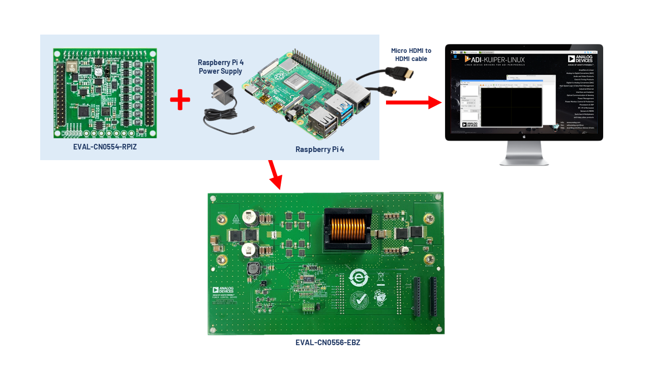
Hardware
Analog I/O module EVAL-CN0554-RPIZ
Raspberry Pi 4 Model B
Raspberry Pi 4 USB-C power supply
Benchtop power supply, up to 56V and 35A
Digital multimeter
Electronic load
MicroHDMI to HDMI cable
Monitor with HDMI display
USB keyboard and mouse
16 GB microSD card
Software
Python 3.7 or newer
Documentation
Software Setup
The input and output voltages and current limits of the CN0556 can be controlled through software. Interfacing CN0556 with the CN0554 analog I/O module enables full control capability. For the device to run, the SD card should be loaded with Analog Devices Kuiper Linux, a distribution based on Raspbian from the Raspberry Pi Foundation. It incorporates Linux device drivers for ADI products as well as tools and other software products designed and created with ease of use in mind. The reasoning behind creating this distribution is to minimize the barriers to integrating ADI hardware devices into a Linux-based embedded system.
Access to the embedded system can be through a remote PC connected either via LAN cable or Wi-Fi.
Downloading and Flashing ADI Kuiper Linux Image on SD Card
In order to control the EVAL-CN0556-EBZ from the Raspberry Pi, you need to install ADI Kuiper Linux on an SD card. Complete instructions, including where to download the SD card image, how to write it to the SD card, and how to configure the system are provided at Kuiper Images.

There is an available Wiki Page which explains in detail on how to download and flash the SD card using Windows or Linux OS: ‘Configuring the SD Card for Raspberry Pi Projects’ in the Formatting and Flashing SD Cards using Windows.
Configuring the SD Card for CN0556
For the Linux kernel to identify the device connected to the expansion header, update the device tree overlay. A Device Tree Overlay contains information about additional connected hardware, the EVAL-CN0556-EBZ for this case. The overlay file is already included in the SD card and just needs to be matched to the EVAL-CN0556-EBZ.
Follow Raspberry Pi, substituting the following lines in config.txt.
This brings up the file in the terminal. Scroll down until the line that
begins with dtoverlay is found; then, whatever it currently is, change
it to:
dtoverlay=rpi-cn0556
Running the Example Scripts using PyADI-IIO
PyADI-IIO is a python abstraction module for ADI hardware with IIO drivers to make them easier to use. This module provides device-specific APIs built on top of the current libIIO python bindings. These interfaces try to match the driver naming as much as possible without the need to understand the complexities of libIIO and IIO.
Follow the step-by-step procedure on how to install, configure, and set up PyADI-IIO and all necessary packages and modules found in PyADI-IIO.
Hardware Configuration
Jumper Settings
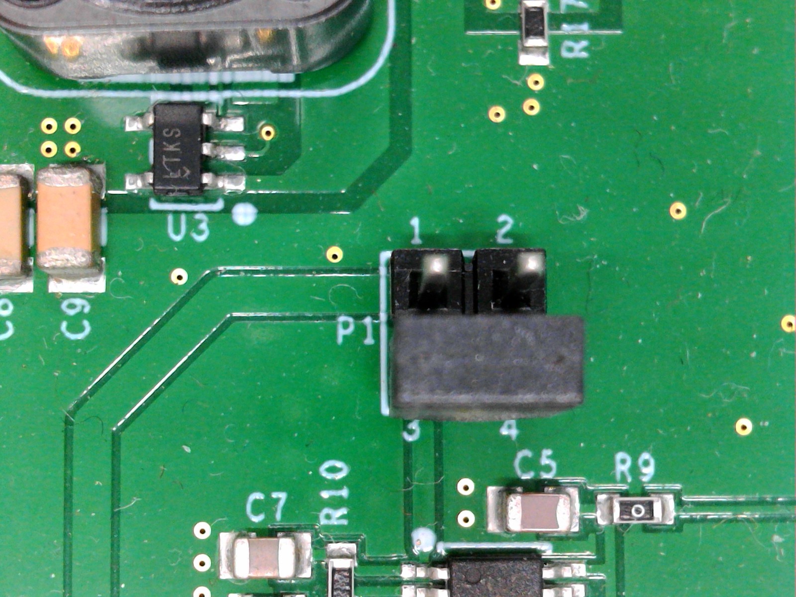
Using 3.3V from the on-board LDO
At P1, check if the shunt placed is in correct position. The shunt should be placed correctly to short Pins 3 and 4. If it is not in proper placement, move the shunt to the correct position before performing the rest of the tests.
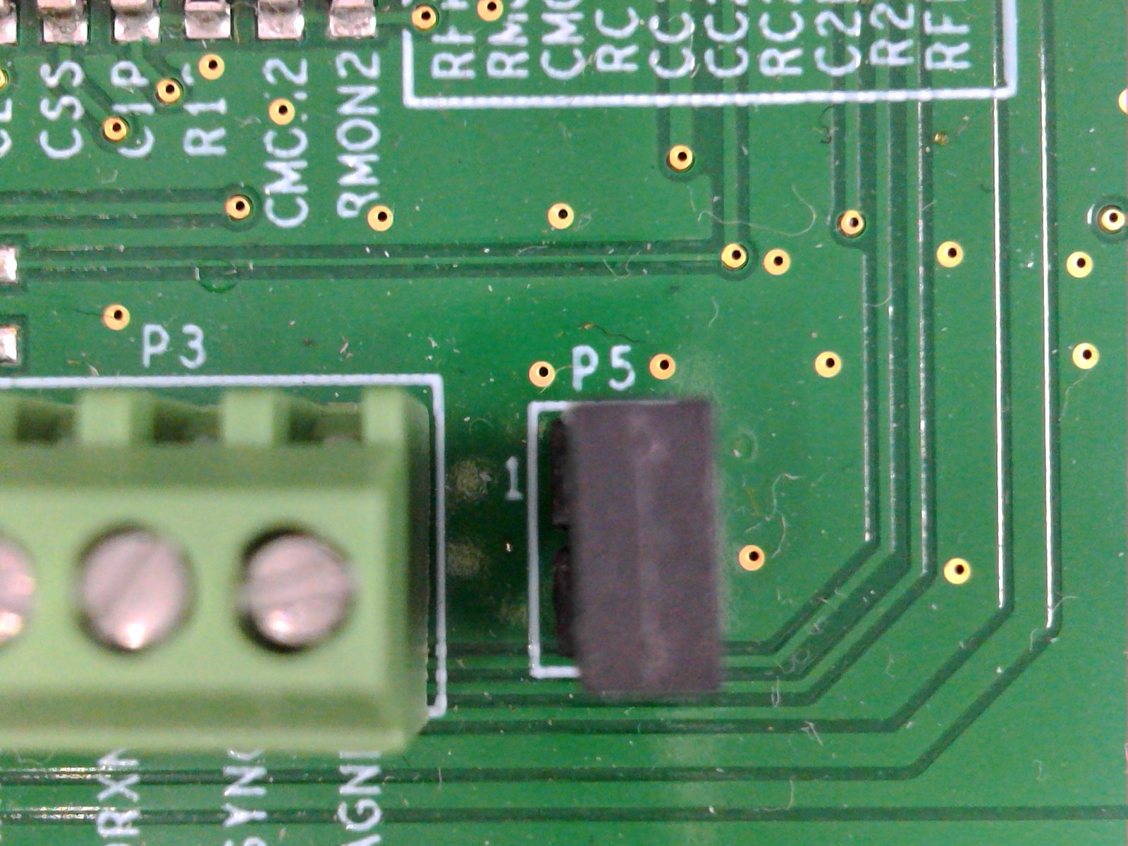
Disabling Current Sharing Capability
The CN0556 enables a masterless fault-tolerant mechanism for sharing output current, following below configuration:
Share Capability |
ISHARE pin |
IGND pin |
|---|---|---|
ENABLED |
ISHARE shorted to IGND with RSHARE resistor in between |
|
DISABLED |
Shorted to INTVCC |
Shorted to AGND |
By default, this capability is disabled in CN0556.
Shunt must be placed on P5 to short ISHARE to INTVCC
Solder jumper P6 is OPEN by default to disconnect ISHARE to IGND:

Solder jumper P7 is SHORTED by default to short IGND to AGND:

Hardware Setup
CN0556 Initial Hardware Setup (BUCK or BOOST Mode)
The EVAL-CN0556-EBZ can be programmed to function in buck or boost mode. Follow below steps to check the buck and boost converter functionality of the EVAL-CN0556-EBZ when connected to the EVAL-CN0554-RPIZ, and its capability to control and monitor the input and output voltage and current.
Buck Mode Setup |
Boost Mode Setup |
|---|---|
CN0556 Buck Mode Setup |
CN0556 Boost Mode Setup |
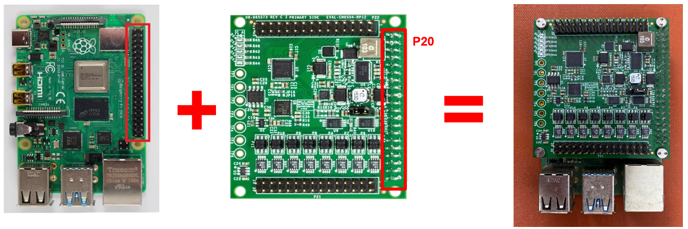
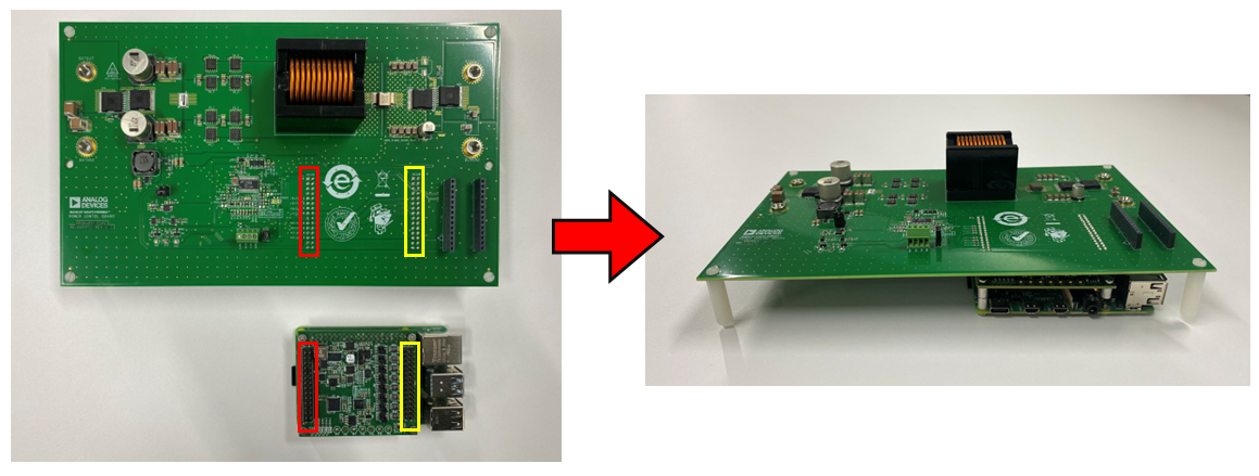
Connect the EVAL-CN0554-RPIZ to the Raspberry Pi 4 using the P20 connector as shown below.
Insert the MicroSD card into the Raspberry Pi’s SD card slot. See Software Setup section for instructions on how to configure the SD Card for CN0556.
Connect the EVAL-CN0556-EBZ on top of the EVAL-CN0554-RPIZ and Raspberry Pi 4 combination based on the connections indicated below.
Ensure that the jumper configuration at P1 and P5 is correct before powering on the device. See Jumper Settings to verify the configuration.
Ensure that the P3 is not shorted by any wire.
Set up the connections to the Raspberry Pi 4.
Connect the MicroHDMI cable to the Raspberry Pi 4 and the other end to the display monitor.
Connect the USB keyboard and a USB mouse to any of the USB ports in the Raspberry Pi 4.
Plug the USB type C power adapter into the Raspberry Pi and wait for it to boot up.
Mode 1: CN0556 in Buck Mode
Hardware Setup (continuation):
Warning
The following steps involve high DC voltages. Follow instructions carefully to prevent hot plugging, which may damage the device by an overvoltage transient.
Prepare a bench top power supply, electronic load, and two digital multimeters.
Ensure that the power supply is completely turned off during the setup.
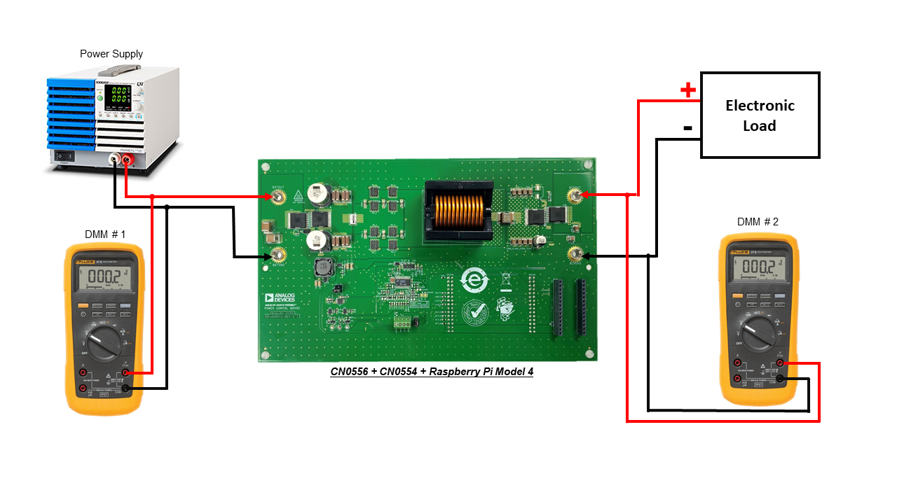
Connect the power supply to V1 terminals (BSTOUT and BSTGND).
Connect the first DMM to the V1 input terminals (BSTOUT and BSTGND).
Connect the electronic load to V2 terminals (BCKOUT and BCKGND).
Connect the second DMM to the V2 output terminals (BCKOUT and BCKGND).
Switch on the multimeter to measure DC voltage and probe the following points after the test program has finished running.
Proceed to Running the Buck Mode Example Script section for step-by-step instructions on how to get measurements.
Running the Buck Mode Example Script
Tip
By default, the example script sets the board into Buck Mode and sets its parameters to its maximum values. You may try to adjust the values after this test. Refer to the table of ranges appropriate for each control function.
Ensure that the power supply is at the V1 left side and the electronic load is at the V2 right side.
Once the Raspberry Pi 4 has finished booting, open the command prompt or terminal and navigate through the examples folder inside the downloaded or cloned pyadi-iio directory.
Turn on the power supply and the electronic load.
Set the power supply at V1 left side to 56V and set the current limit to 2A. Do not enable the power supply yet.
Set the electronic load at the right side to 0.1A.
Enable the electronic load.
Navigate into the cn0556_examples folder inside the pyadi-iio > examples directory.
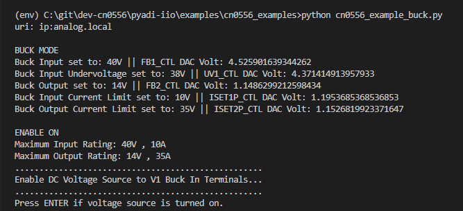
Run the example script using the command:
~/pyadi-iio/examples/cn0556_examples$
python cn0556_example_buck.pyThe details of the current and voltage set at the output will be displayed.
Enable the output of the power supply into the V1 terminals.
Check the DMM at the output V2 side. It should read approximately 14V.
If the reading is not 14V (or almost 0V), try to slowly increase the input DC voltage at V1 to up to 58V. Once the output is 14V, decrease the input voltage at V1 to 56V again.
Once the power supply is enabled, and the DMM reads approx. 14V, press the ENTER key.

The input and output voltage and current at the V1 and V2 side will be printed in the command window.
The board will continuously regulate the output voltage to 14V unless CN0556 is turned off.
Press ENTER to disable and turn off the board.
Turn off the power supply and the electronic load. Make sure that the settings of the power supply are at 0V and 0A limit, as well as the electronic load to 0A.
Summary of Buck Mode Functions
The CN0556 buck mode pyadi-iio example script enables the user to control the input and output parameters of the board, as well as to measure the current and voltage at the input and output terminals. The summary of the CN0556 functions for Buck Mode can be found below:
Mode 2: CN0556 in Boost Mode
Hardware Setup (continuation):
Warning
The following steps involve high DC voltages. Follow instructions carefully to prevent hot plugging, which may damage the device by an overvoltage transient.
Prepare a bench top power supply, electronic load, and two digital multimeters.
Ensure that the power supply is completely turned off during the setup.
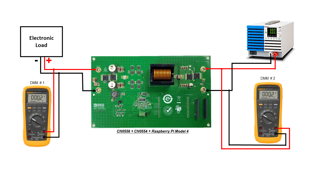
Connect the power supply to V2 terminals (BCKOUT and BCKGND).
Connect the second DMM to the V2 input terminals (BCKOUT and BCKGND).
Connect the electronic load to V1 terminals (BSTOUT and BSTGND).
Connect the first DMM to the V1 output terminals (BSTOUT and BSTGND).
Switch on the multimeter to measure DC voltage.
Proceed to Running the Boost Mode Example Script section for step-by-step instructions on how to get measurements.
Running the Boost Mode Example script
Tip
By default, the example script sets the board into Boost Mode and sets its parameters to its maximum values. You may try to adjust the values after this test. Refer to the table of ranges appropriate for each control function.
Ensure that the power supply is at the V2 right side, and the electronic load is at the V1 left side.
Once the Raspberry Pi 4 has finished booting, open the command prompt or terminal and navigate through the examples folder inside the downloaded or cloned pyadi-iio directory.
Turn on the power supply and the electronic load.
Set the power supply at V2 left side to 14V and set the current limit to 10A. Do not enable the power supply yet.
Set the electronic load at the right side to 0.1A.
Enable the electronic load.
Navigate into the cn0556_examples folder inside the pyadi-iio > examples directory.
Run the example script using the command:
~/pyadi-iio/examples/cn0556_examples$
python cn0556_example_boost.pyThe details of the current and voltage set at the output will be displayed.
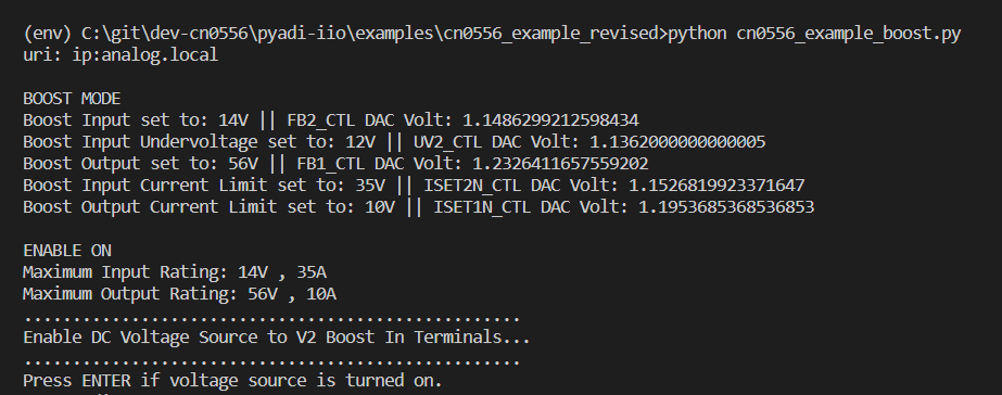
Enable the output of the power supply into the V2 terminals.
Check the DMM at the output V1 side. It should read approximately 56V.
Once the power supply is enabled, and the DMM at the left side reads approx. 56V, press the ENTER key.

The input and output voltage and current at the V1 and V2 side will be printed in the command window.
The board will continuously regulate the output voltage to 56V unless CN0556 is turned off.
Press ENTER to disable and turn off the board.
Turn off the power supply and the electronic load. Make sure that the settings of the power supply are at 0V and 0A limit, as well as the electronic load to 0A.
Summary of Boost Mode Functions
The CN0556 boost mode pyadi-iio example script enables the user to control the input and output parameters of the board, as well as to measure the current and voltage at the input and output terminals. The summary of the CN0556 functions for Boost Mode can be found below:
Schematic, PCB Layout, Bill of Materials
Download
EVAL-CN0556-EBZ Design & Integration Files
Schematics
PCB Layout
Bill of Materials
Allegro Project