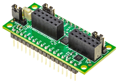
FTHR-PMD-INTZ
Feather to PMOD Adaptor Board.
Overview
The FTHR-PMD-INTZ is an add-on adapter board especially built for the MAXIM MCU boards. Maxim Feather Boards, namely the MAX32630FTHR, MAX32650FTHR, MAX32655FTHR, MAX32666FTHR, and MAX78000FTHR, are very small form factors called “feathers”, and they require special connectors to be used with other Pmod boards.
This interposer board provides such solution and allows interfacing with up to two Pmod boards via SPI or I2C interface. Furthermore, this add-on adapter board adheres to the standards, such as the Digilent Pmod™ Interface Specification and Adafruit Feather Specification.
Adapter Board Hardware
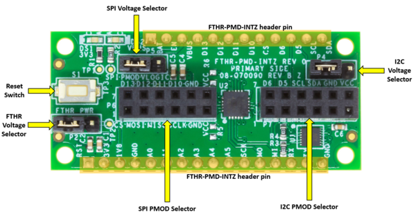
Power Configuration
The circuit is powered by the voltage coming from the Maxim Featherheaders.
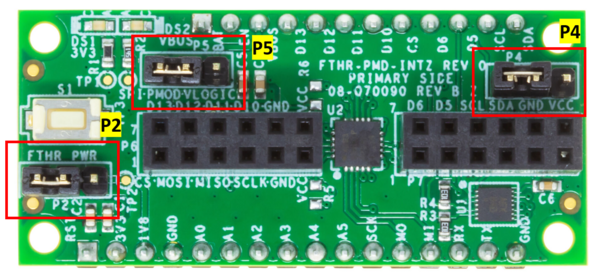
The table below lists the power configuration for this interposer board. The default voltage configuration for all is 3V3.
Part |
Description |
Left Connection |
Right Connection |
P2 |
Feather Voltage Selector |
3V3 |
1V8 |
P4 |
I2C PMOD Voltage Selector |
3V3 |
VBUS (5 V) |
P5 |
SPI PMOD Voltage Selector |
3V3 |
VBUS (5 V) |
SPI Pmod Connector (P6)
Connect Pmod devices that use SPI interface to the left-hand side Pmod connector, as shown below.
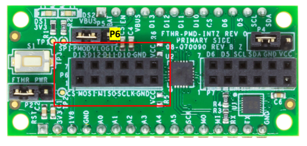
The table below lists the corresponding pin assignment.
SPI Pmod Connector (P6) Pinout |
|||
|---|---|---|---|
Pin Number |
Pin Function on FTHR-PMD-INTZ |
Pin Number |
Pin Function on FTHR-PMD-INTZ |
1 |
CS. SPI Chip select #1 from MAXFTHR to the Pmod device. |
7 |
SPI_GPIO0. Interrupt Signal from the Pmod device to the MAXFTHR |
2 |
MOSI_GPIO1. SPI data from MAXFTHR to the Pmod device. |
8 |
SPI_GPIO1. Reset Signal from MAXFTHR to Pmod device |
3 |
MISO. SPI data from MAXFTHR to the Pmod device. |
9 |
SPI_GPIO2. SPI Chip select #2 from MAXFTHR to the Pmod device. |
4 |
SCLK. SPI Clock from MAXFTHR to the Pmod device. |
10 |
SPI_GPIO3. SPI Chip select #3 from MAXFTHR to the Pmod device. |
5 |
GND. Ground |
11 |
GND. Ground |
6 |
VCC. Connected to 3V3 or VBUS from MAXFTHR (shorted in P5) |
12 |
VCC. Connected to 3V3 or VBUS from MAXFTHR (shorted in P5) |
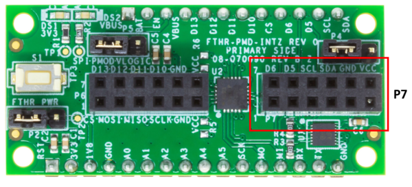
I2C Pmod Connector (P7)
Pmod devices that use I2C interface should be connected to the right Pmod connector.
The table below lists the corresponding pin assignment.
I2C Pmod Connector (P7) Pinout |
|||
|---|---|---|---|
Pin Number |
Pin Function on FTHR-PMD-INTZ |
Pin Number |
Pin Function on FTHR-PMD-INTZ |
1 |
I2C_GPIO0. Interrupt Signal from the Pmod device to the MAXFTHR. |
7 |
I2C_GPIO0. Interrupt Signal from the Pmod device to the MAXFTHR. |
2 |
I2C_GPIO1. Reset Signal from the MAXFTHR to the Pmod device. |
8 |
I2C_GPIO1. Reset Signal from the MAXFTHR to the Pmod device. |
3 |
SCL. I2C Clock from the MAXFTHR to the Pmod device. |
9 |
SCL. I2C Clock from the MAXFTHR to the Pmod device. |
4 |
SDA. I2C Data from the MAXFTHR to the Pmod device. |
10 |
SDA. I2C Data from the MAXFTHR to the Pmod device. |
5 |
GND. Ground |
11 |
GND. Ground |
6 |
VCC. Connected to 3V3 or VBUS from MAXFTHR (shorted in P4) |
12 |
VCC. Connected to 3V3 or VBUS from MAXFTHR (shorted in P4) |
Schematic, PCB Layout, Bill of Materials
Download
FTHR-PMD-INTZ Design & Integration Files
Schematics
PCB Layout
Bill of Materials
Allegro Project
LTspice Simulation File