ADI Long Range Wireless Radio Software User Guide
The ADI Long Range Wireless Radio Software is accompanied by an open-source software stack and associated collaterals, enabling a complete experience from evaluation and prototyping all the way to production firmware and applications development.
The system‘s firmware is based on Analog Devices’ open-source programming and debugging tool called Maxim Micro Software Development Installer Kit (MaximSDK), which includes most of the tools required for embedded code development and7 debugging as well as libraries enabling host-side connectivity for system configuration and data transfer over UART.
Software Setup
Requirements
Host PC (Windows 10 or later) with administrator access
1920 by 1080 or greater screen resolution, recommended
with downloaded:
RAK5146 PiHAT Kit consisting of
One (1) RAK5146 SPI module
One (1) RAK5146 PiHAT
Long range and GPS antenna
Spacers and nuts kit for secure mounting of the PiHAT
One (1) Raspberry Pi 4 with 5V Type-C Power supply
One (1) Micro SD card
One (1) LAN cable
One (1) Micro USB to USB cable
Firmware Setup
Make sure you have completed the steps described in Hardware Setup before proceeding with the steps listed below.
Download and install the UART serial monitor. This will be needed to view the activity of the Sensor Node via UART serial interface.
Note
This setup uses the Real Term serial monitor, but other UART serial terminals may also be used. Real Term requires .NET framework to be installed on the Host PC to function properly. Make sure to install this requirement before using this serial terminal: .NET Framework 4.6.2
Download the
AD-MAX32WISE-SLZ Firmware (Rel1.0.0)and extract the file to a known location.Double-click on the
AD-MAX32WISE-SLZ-Rel1.0.0.exe.and follow the installation prompts.Go to
C:\\Analog Devices\\AD-MAX32WISE-SLZ-Rel1.0.0\\Software\\ad_max32wise_src\\binand find the firmware you need to load based on the chosen sensor node. The firmware folder should contain the BIN, ELF, and HEX file.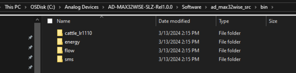
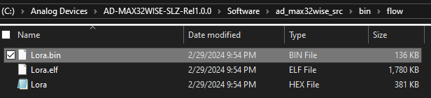
Go to My Computer and search for the DAPLINK drive. Drag and drop (or copy and paste) the .bin or .hex firmware files directly into the DAPLINK drive. To check if the flashing is successful, check the DAPLINK directory and make sure there is no FAIL.TXT file. In case there is, repeat the drag and drop step.
Reset the Base Board by pressing the S1 reset button.
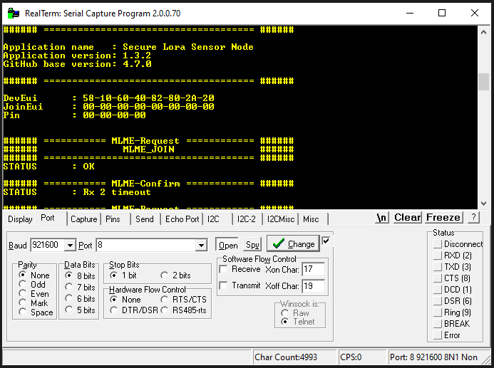
Open the UART serial monitor to check if the firmware has been loaded correctly. Make sure to use the following settings:
Ports: Take note of the COM port used by checking the Device Manager
Baud Rates and Ports: set to 921600
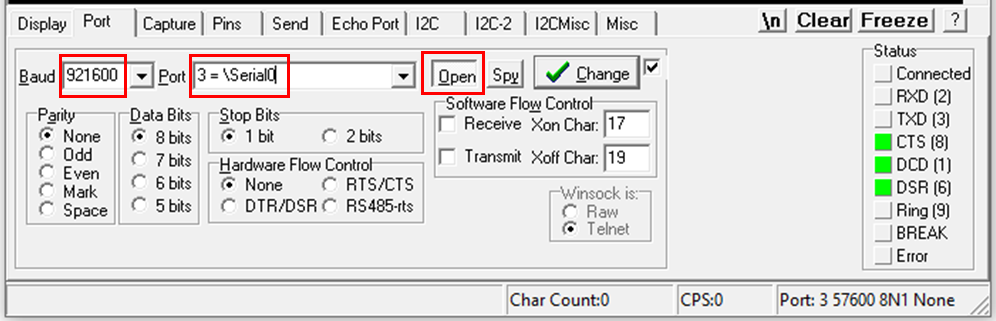
Display formatting: set to ANSI
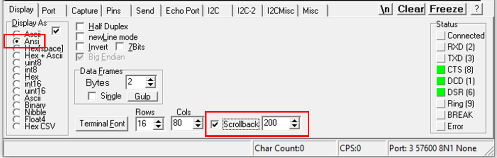
Once configured, open the serial monitor.
Take note of the DevEUI (64-bit end-device identifier). This will be used later during the gateway setup. To redisplay the DevEUI on the screen, reset the MAX32670-SX-ARDZ Base Board by pressing the S1 button.
Gateway Setup
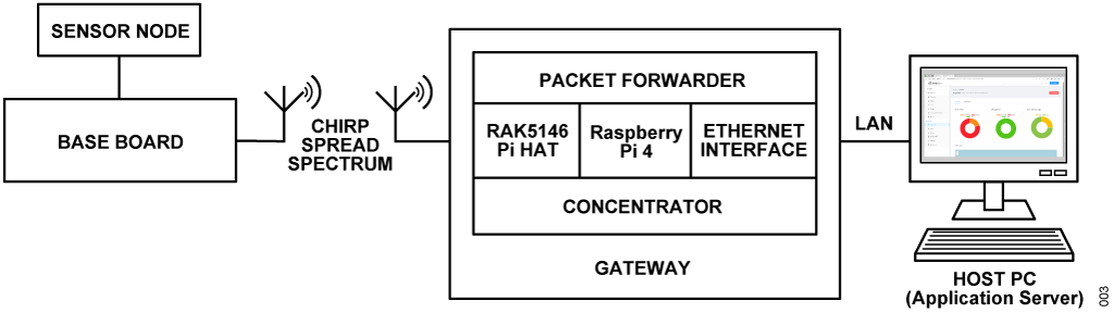
To demonstrate the long range radio communication capability based on the chirp spread spectrum (CSS) technique, a gateway connection must first be established.
A gateway transmits the data received from the Base Board and Sensor Nodes to the internet or to your local application server. In order to do this, you must properly set up the Concentrator and the Host MCU.
This setup uses the Raspberry Pi 4 as the hardware and ChirpStack v4 as the gateway OS. Follow below instructions to set up the gateway connection and use the web interface for your applications.
Requirements
Hardware
RAK5146 PiHAT Kit consisting of
RAK5146 SPI module
RAK5146 PiHAT
IPEX long range antenna
IPEX GPS antenna (optional if RAK5146 SPI with GPS is selected)
Spacers and nuts kit for secure mounting of the PiHAT
-
with Power supply (5V)
with Type-C cable
Host PC with administrator access
Windows 10 OS or later
Microsoft .Net Framework 4.6.2
1920 by 1080 or greater screen resolution, recommended
Micro SD card (16 GB or larger)
USB keyboard and mouse
LAN cable
Software
Balena Etcher image writing tool
Documentation
Hardware Assembly of the Concentrator
What is a Concentrator?
A concentrator is an essential part of any gateway because it enables the reception and transmission of data packets from and to the end devices. It can receive multiple signals to serve a large number of end device.
In this example, the RAK5146 PiHAT Kit and the Raspberry Pi 4 act as the concentrator.
Follow below steps to setup the concentrator hardware:
Insert the RAK5146 SPI module into the mPCIe slot on the RAK2287 Pi HAT. Make sure the card fits snugly into the connector.
Gently press the SPI module down and fasten it using the screws provided.
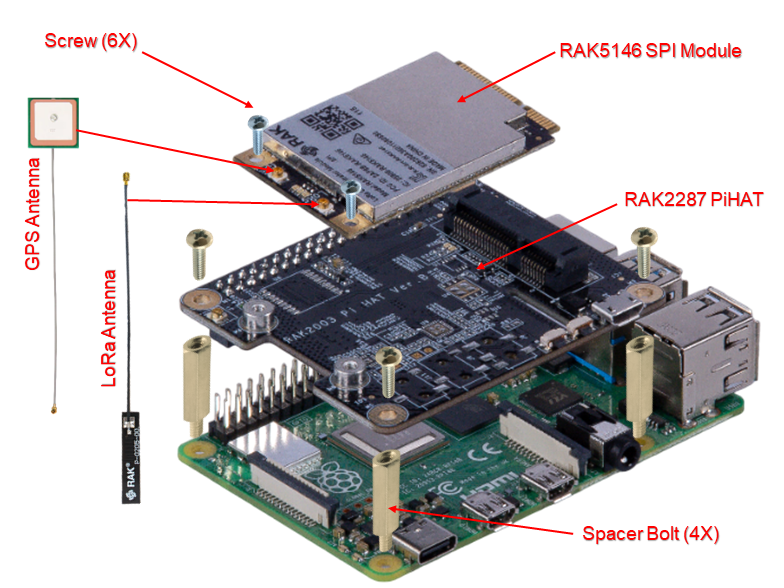
Connect the RAK5146 PiHAT to the Raspberry Pi using the 40-pin connector.
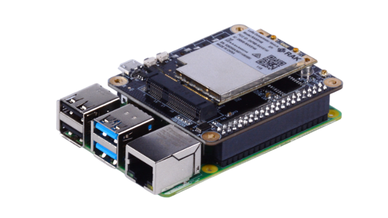
Connect the Raspberry Pi to the Host PC using the LAN cable.
Power on the Raspberry Pi by plugging in a 5V power supply using the Type-C USB connector.
Imaging the SD Card with ChirpStack OS
Download the Chirpstack Gateway OS version 4.1.1 or latest
Tip
This setup uses the Raspberry Pi 4B Full Image
Download and install Balena Etcher image writing tool. Note that this setup uses the Balena Etcher tool for writing the image on SD card. You can use other image writing tools of your choice.
Run the Balena Etcher tool.
Insert the micro SD card into the Host PC.
Click Flash from file from the options shown in the interface.
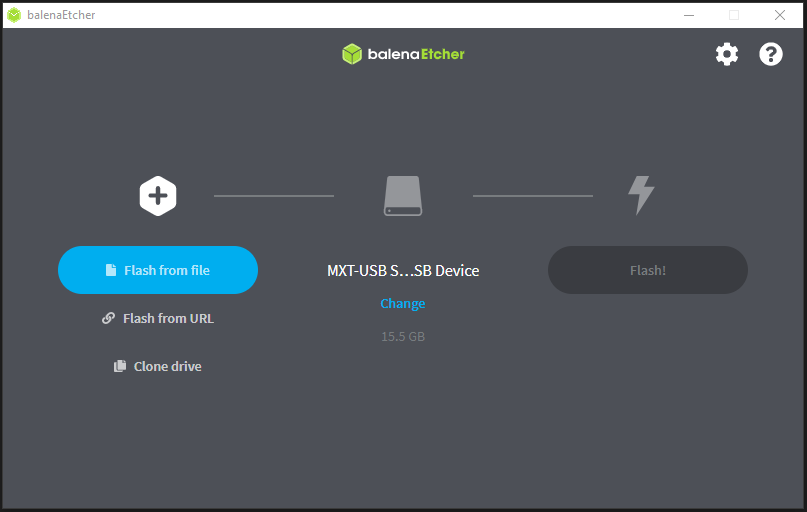
Navigate to the location where the downloaded Chirpstack Gateway OS is saved.
Select target and choose the targeted micro SD card drive.
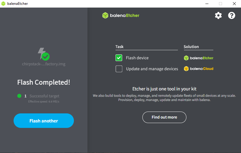
Click Flash to start the burning process of the image in the chosen SD card.
Wait until it is done.
Tip
In case the flashing fails, consult this guide to resolve the issue: Balena Etcher FAQs
Note
After the first boot, the gateway might reboot automatically to apply some changes. The Full Image will set up the PostgreSQL database on its first boot. This could take a couple of minutes and during this time the gateway will be less responsive.
Gateway Configuration
Insert the imaged SD card on the designated slot on the Raspberry Pi.
Connect the Host PC to ChirpStack WiFi.
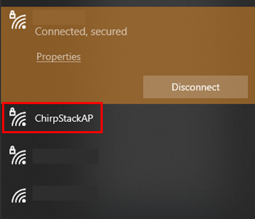
Tip
When prompted to enter password, use ChirpStackAP (case-sensitive).
Access the ChirpStack open network and check its assigned IP Address through SSH connection. Open CMD on the Host PC.
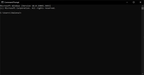
Establish Secure Shell (SSH) connection using admin account and ChirpStack static IP. Enter this on the terminal:
ssh admin@192.168.0.1SSH connection will ask for the password input. Use below credentials:
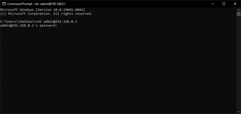
Username: admin
Password: admin
StaticIP: 192.168.0.1
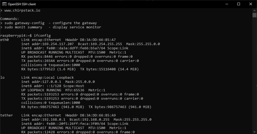
Once connected, check the assigned ChirpStack IP by typing ifconfig
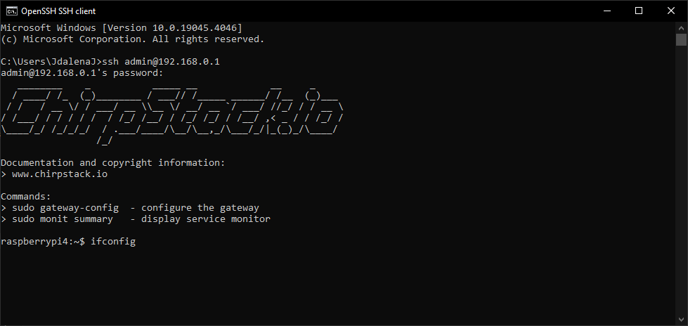
This will show all configs, look for
eth0and save the IP address assigned to it.Tip
In this example, the IP assigned is 169.254.117.207. By saving the assigned IP, you’ll be able to establish an SSH connection on your machine without having to connect through the ChirpStack open network.
Open the Raspberry Pi terminal, then enter
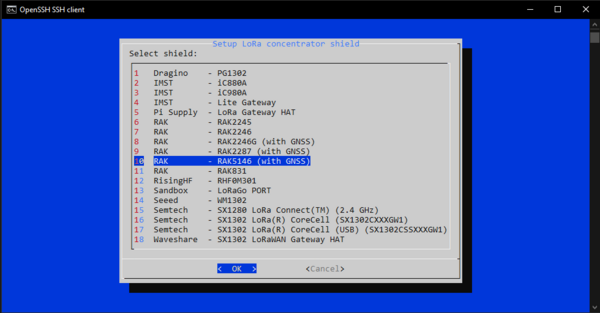
sudo gateway-configIn the main menu, choose
Setup concentrator shield.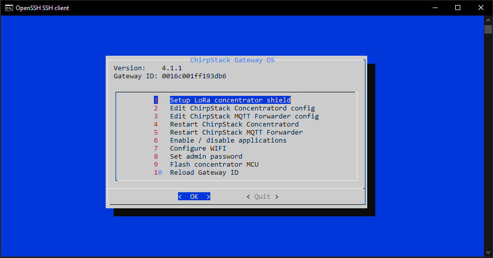
Choose RAK5146 (with GNSS).
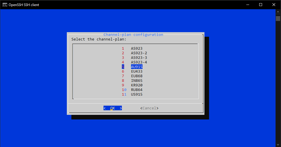
Choose AU915.
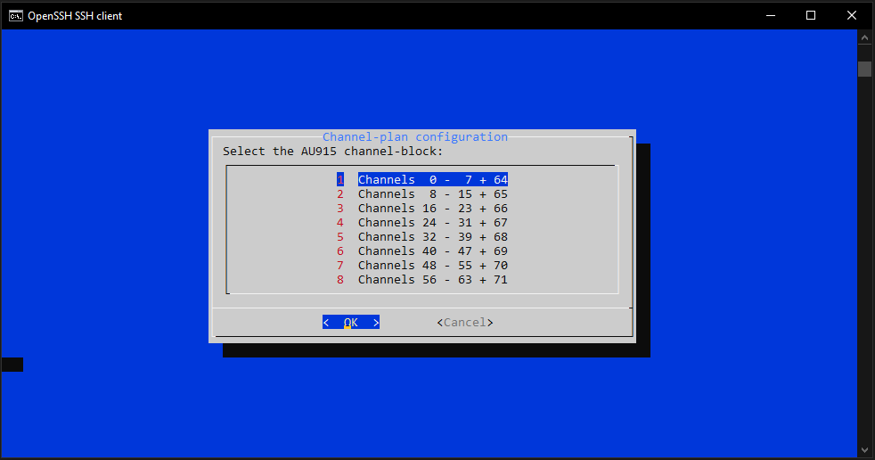
Choose Channels 0 to 7 + 64.
The Concentrator restarts and goes back to the main menu.
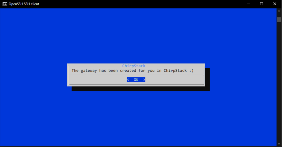
Quit the main menu.
If you have properly configured the gateway and installed the required SD card image, then you are ready to use the ChirpStack Network Server.
Setting up a Self-Hosted Application Server
Requirements
Raspberry Pi 4 with ChirpStack version 4.1.1 IO booted
Host PC with Admin Access
LAN cable
Configuring Host PC for the Gateway
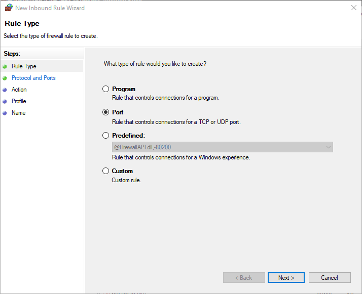
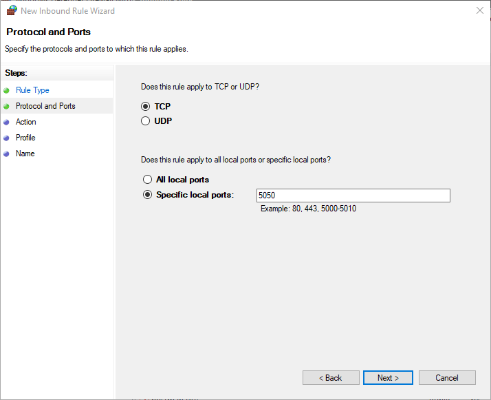
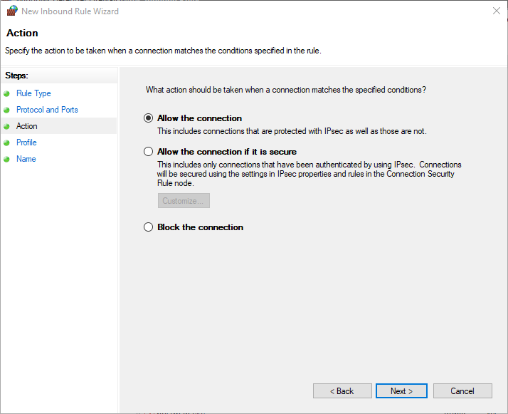
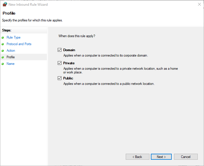
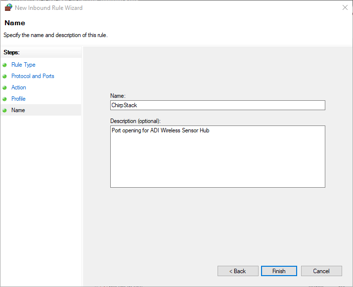
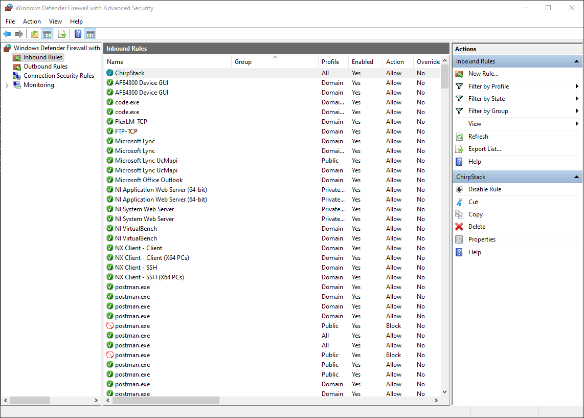
Enabling Port 5050 facilitates seamless communication between the Gateway and the Local server machine via the specified open Port connection (in this instance, 5050). The selection of port 5050 is based on its recommendation, ensuring it falls within a universally understood range of ports that are not commonly used for standard purposes elsewhere.
Access Advance Firewall settings in your computer.
Create a new Inbound Rule.
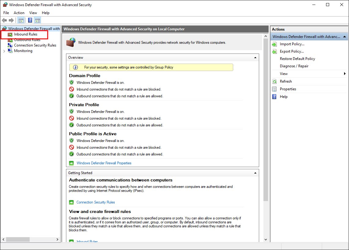
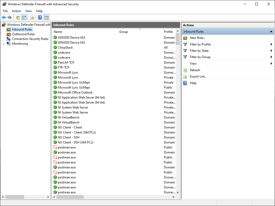
Follow the steps below to configure the device.
Installing the GUI and Accessing the Gateway
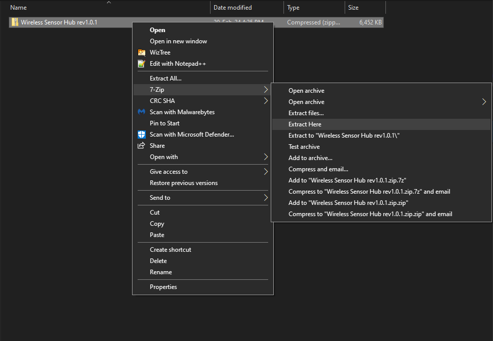
Download and extract the ADI Wireless Sensor Standalone Software
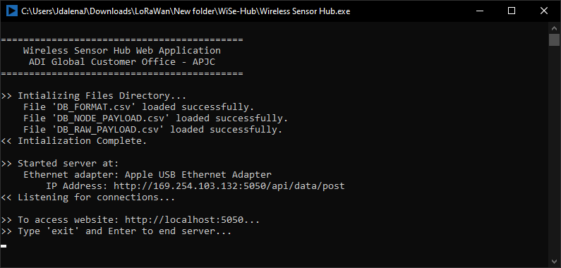
Once extracted, run the ADI Wireless Sensor Standalone Software with administrator privileges.
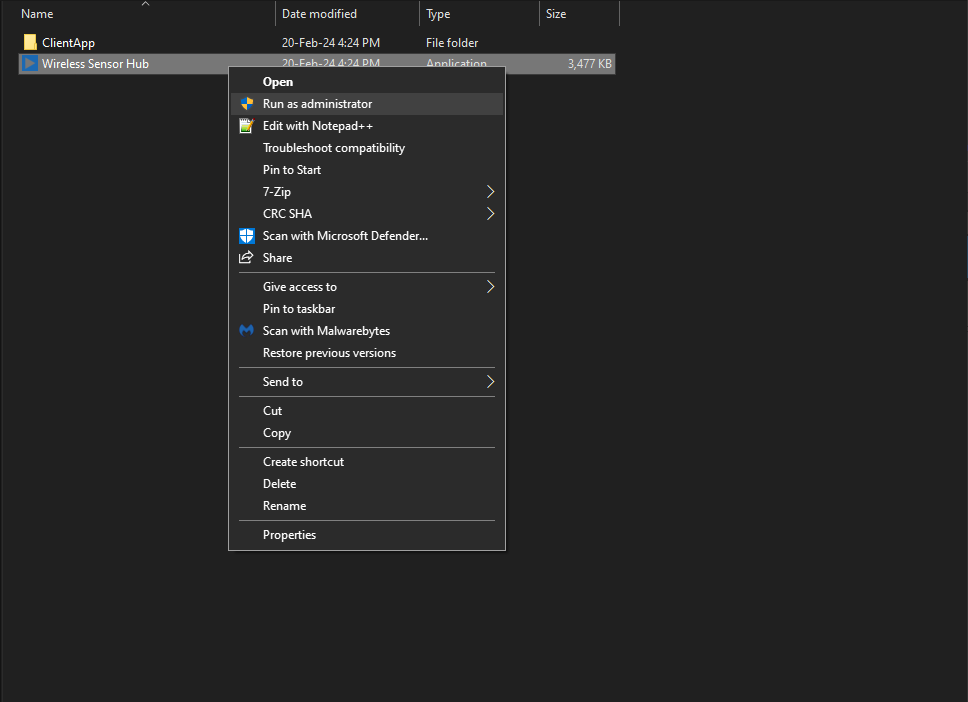
This will start the initialization process and run the process on your PC.
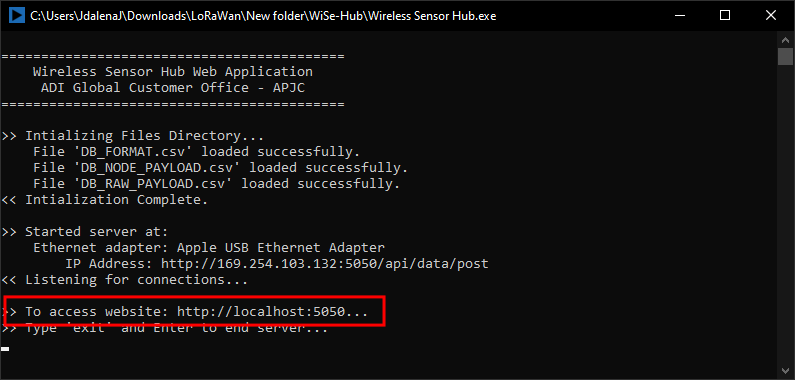
Check the IP address assigned to the Raspberry Pi gateway. Take note that the server will show all connections available, select the IP of the connector you used. In this example, it’s the Apple USB Ethernet Adapter. This information will be used in Step 5.3.4 to integrate data from the gateway to the GUI.

Use the assigned ChirpStack IP address saved earlier to access its configuration interface.
Tip
In this example, it is 169.254.117.207. If you haven’t saved the IP address, revisit Steps 3 to 7 in Gateway Configuration section
Add the ChirpStack Port (8080) to the end of IP address. Open a page in the browser using the URL : 169.254.117.207:8080
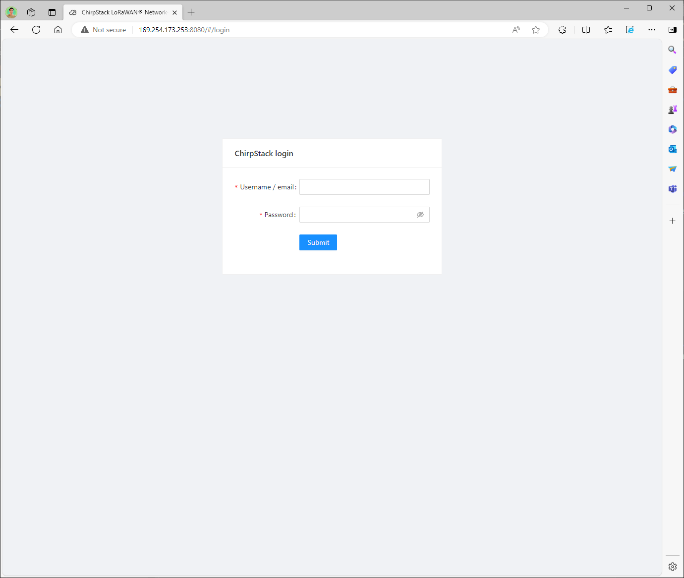
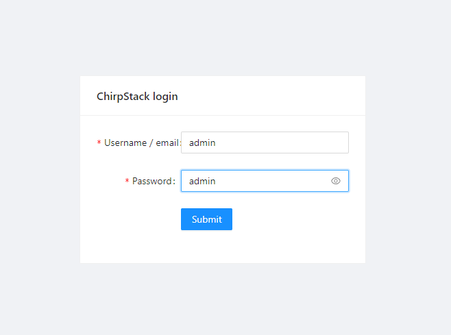
This will open the login page. Enter the same credentials we used to establish an SSH connection with the ChirpStack Gateway.
Connecting a Sensor Node to the Gateway
This section describes how to connect your sensor node to ChirpStack and how to validate that it can successfully send data. At this point, it is assumed that you have a working ChirpStack environment with a connected gateway.
Creating a Device Profile
Before you can add a device (sensor node) to ChirpStack, you need to create a device-profile. In general, it is a good practice to create separate device-profiles for different types of devices (sensor nodes). A device-profile contains the capabilities of your device.
Once you are in the ChirpStack landing page, navigate to the Applications tab.
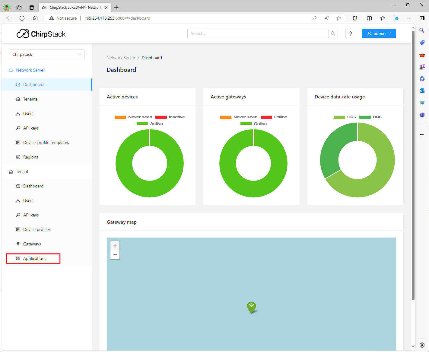
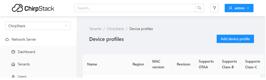
Click Device profiles under the Tenant category, as shown below.
Click on the Add device profile button.
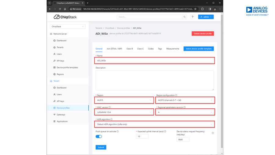
Answer all required information under the General tab, and then click Submit once done. For the Name, enter the desired sensor node name.
The following shows the other configuration required to add a sensor node:
Region: AU915
Region Configuration: AU915 (channels 0-7 +64)
MAC Version: LoRaWAN 1.0.4
Regional parameters revision: A
ADR algorithm: Default ADR algorithm (LoRa only)
Expected uplink interval (sec): 10
Device-status request frequency (req/day): 8640
Enrolling Device Applications
After adding a device, click the Applications option under Tenant.
Click on the Add application button.
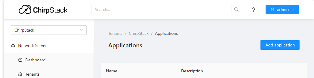
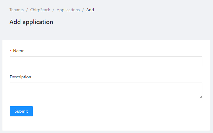
Write the desired Application Name on the space provided. Hit Submit once done.
Open the Application created and add a device. Ensure that in naming the devices, you must include a SPECIFIC KEYWORD (not case-sensitive) to distinguish which sensor nodes will be shown on the GUI. The naming codes of sensor nodes are as follows:
Sensor
Code Name
EV-FLOWMETER-ARDZ
flow
EV-STRUCTURAL-ARDZ
sms
EV-CATTLETAG-ARDZ
cattle
EV-ADE9000SHIELDZ
e-meter
The following details are also needed:
Name: previously defined application name set from the previous steps
Device EUI (EUI64): unique serial number of the device
Device profile: previously defined device profile set from the previous steps
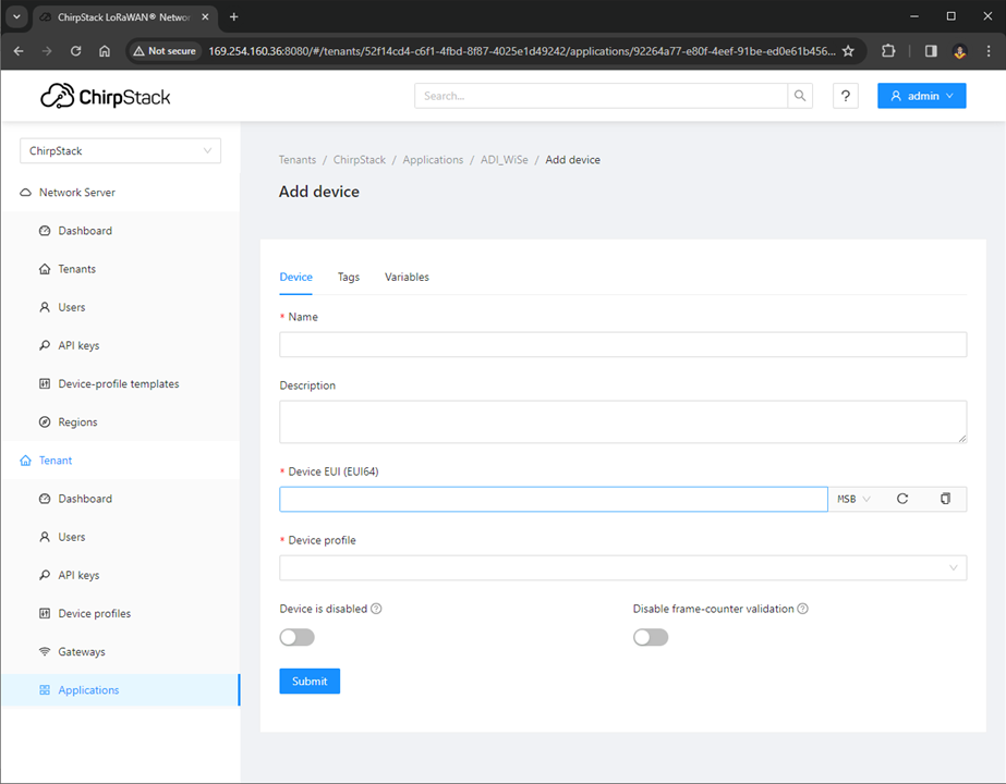
Once done, click Submit.
Tip
For OTAA devices, confirm that when the device tries to OTAA activate, you see a JoinRequest message followed by a JoinAccept message. If you do not see a JoinRequest and JoinAccept, click on the Flush OTAA devices button.
Enter the Application key and hit Submit once done.
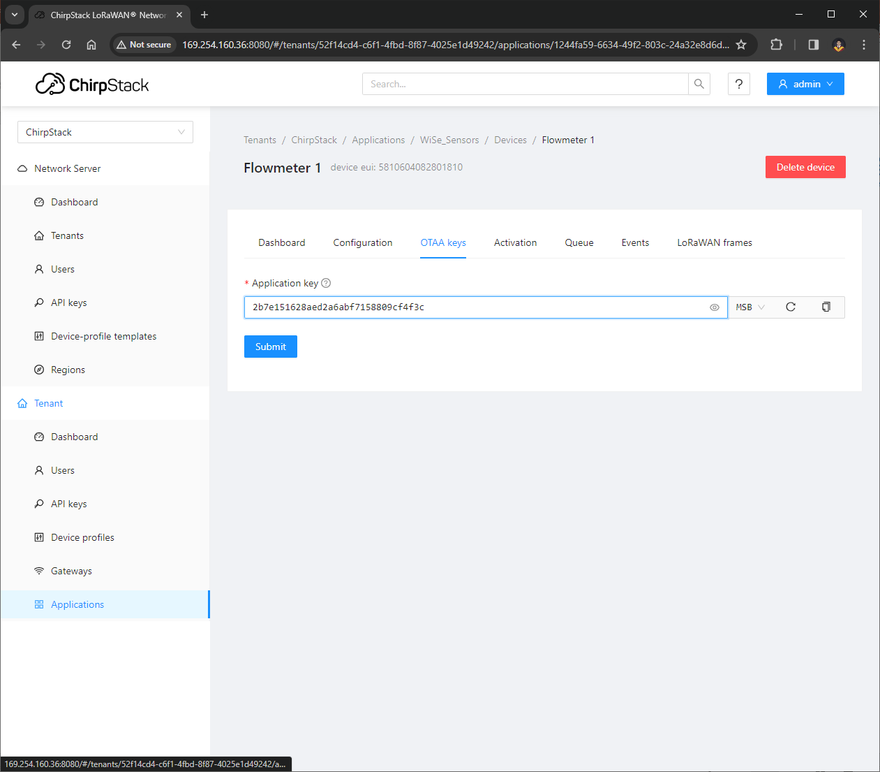
Note
For this demo, the Application key is 2b7e151628aed2a6abf7158809cf4f3c
The App Key included in the LoraMAC was used as is for the purpose of evaluation. Users can generate the App Key and add it in the source code on their own.
Setting up Local Host URL for the Application Server
Once you are in Applications tab, select and open WiSe_Sensors.
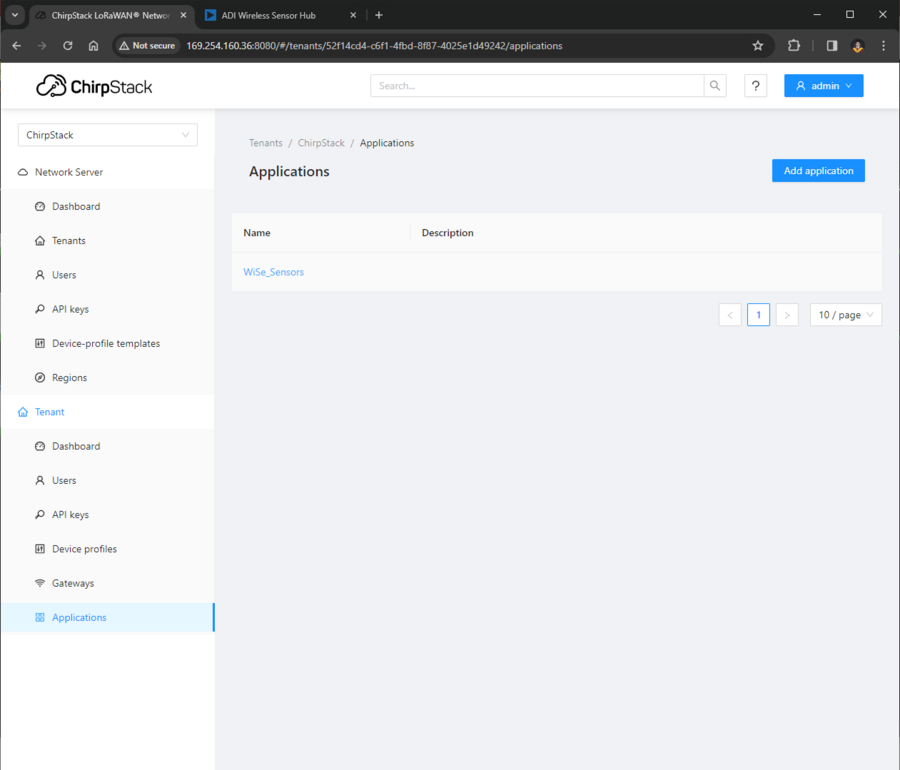
Inside ADI_SENSOR_NODE application, navigate to the Integrations tab.
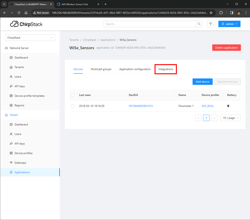
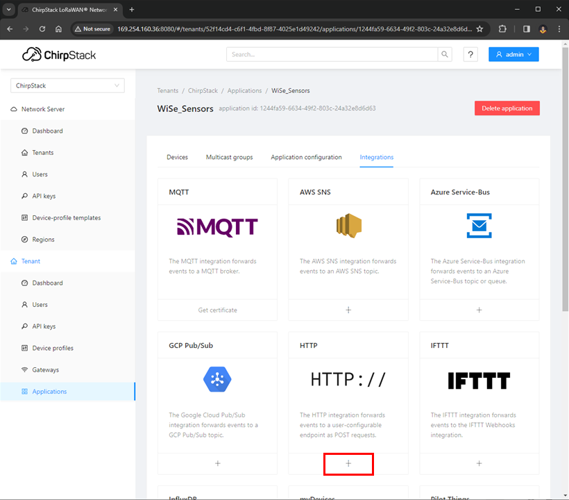
In Integrations tab, select the edit button in the HTTP Configuration section.
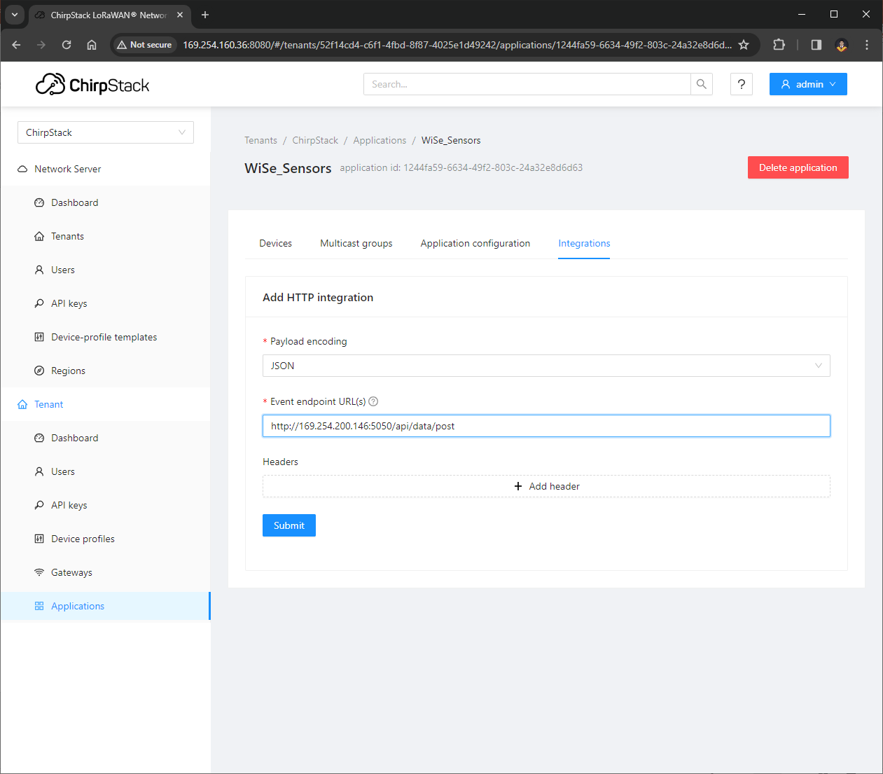
Change the Event Endpoint URL to the IP of the adapter your gateway is connected.
Tip
In this example, it is the IP of the Apple Network Adapter, which is http://169.254.178.157:5050/api/data/post.

After updating the HTTP Integration endpoint URL, submit the changes by pressing the submit button below.
A pop-up message will appear saying HTTP Integration updated.
Now you can access the Local Application Server by using the local host URL shown during initialization.
Open your browser and enter the URL http://localhost:5050. Now you’ll be able to see and monitor your active nodes.
Local Application Server GUI
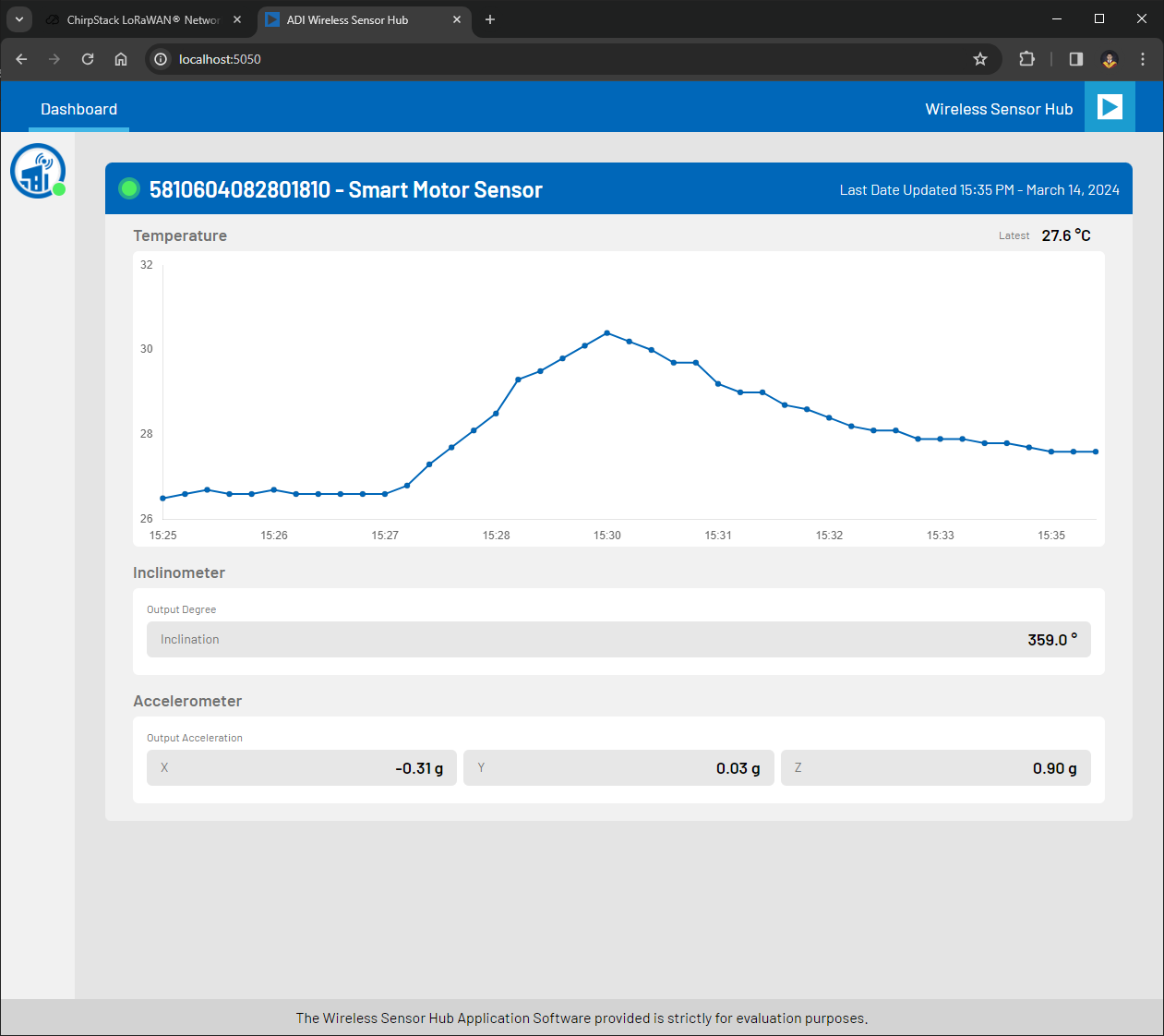
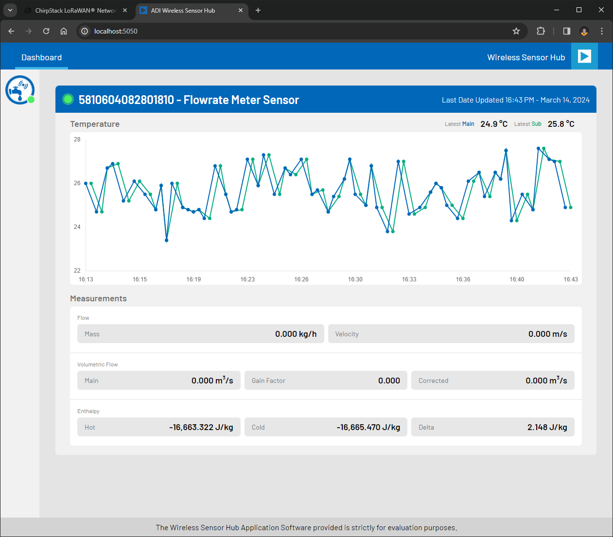
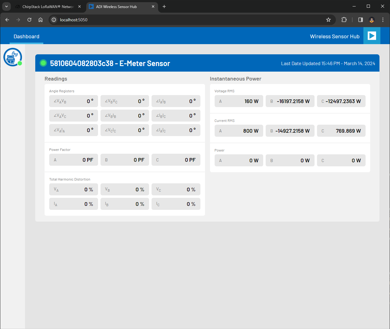
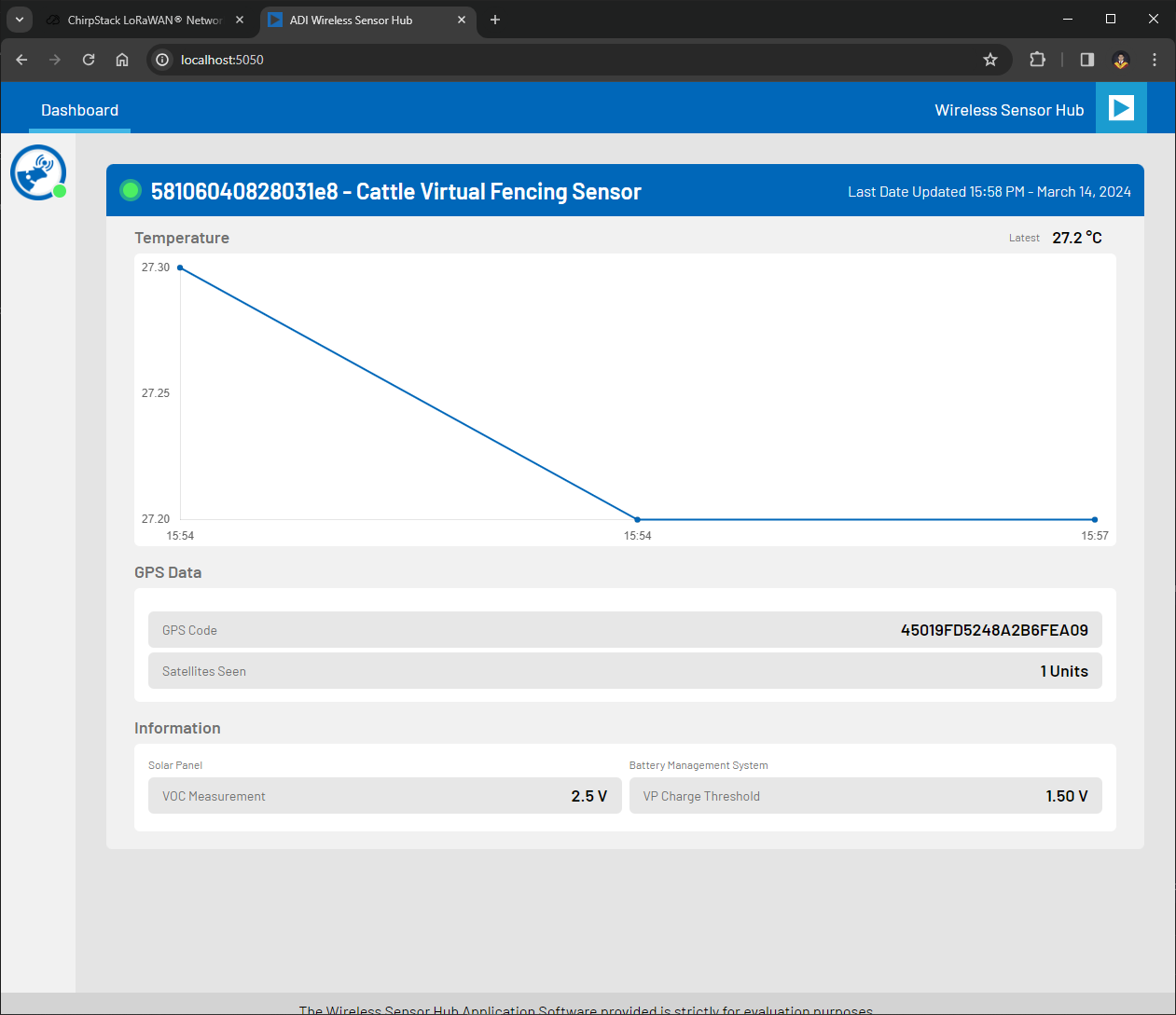
After you have successfully added a device (sensor node) and an application in the Chirpstack network, you will be able to view the graphical representation of the data collected by the sensor, as shown in the example below:
Smart Motor Sensor GUI
Flow Meter Sensor GUI
E-meter Sensor GUI
Cattle Tag Sensor GUI
FAQs
- Q. Why is the serial application not responding after opening the port?A. It usually happens whenever the power of the base board is not enough to operate the board.
- Q. Can we use other gateways aside from ChirpStack?A. Customers are not limited to use ChirpStack gateway, it is possible to use other gateways available in the market.
- Q. What maximum number a gateway can handle?A. It depends on the channels available per assigned region and the time division set by the user on sending data from the nodes to gateway.
- Q. Is there another way to see the GUI without using the local setup?A. The GUI can also be accessed through cloud service, but it is not supported by ADI.
- Q. What is the maximum distance the gateway and nodes can communicate?A. The gateway and nodes’ maximum and effective range may vary depending on the modulation parameters, transmit power, antenna gain, environmental conditions, and obstacles present in the communication path. In practice, it can reach several kilometers in rural areas with a clear line of sight. The effective range may be shorter in urban areas where obstacle and interference are present.