ZCU102 Quick start
All the products described on this page include ESD (electrostatic discharge) sensitive devices. Electrostatic charges as high as 4000V readily accumulate on the human body or test equipment and can discharge without detection. Although the boards feature ESD protection circuitry, permanent damage may occur on devices subjected to high-energy electrostatic discharges. Therefore, proper ESD precautions are recommended to avoid performance degradation or loss of functionality. This includes removing static charge on external equipment, cables, or antennas before connecting to the device.
This guide provides quick instructions on how to setup the EVAL-ADRV903x on:
Using Linux as software
Necessary files
Note
The SD card includes several folders in the root directory of the BOOT partition. In order to configure the SD card to work with a specific FPGA board and ADI hardware, several files must be copied onto the root directory. Using the host PC, drag and drop the required files onto the BOOT partition, and use the EJECT function when removing the SD card from the reader.
The following files are needed for the system to boot:
HDL boot image:
BOOT.BINLinux Kernel image:
ImageLinux device tree:
system.dtb
They can either be taken from the SD card – already generated by us, or you can build them manually:
Instructions on how to choose the boot files from the SD card can be found in the Platform-Specific Manual Steps section from here: Hardware Configuration.
Instructions on how to manually build the boot files from source can be found here:
Important
Some projects provide multiple devicetree files in the SD card’s boot folders. Make sure you select the devicetree that matches your specific use case.
Required Software
SD Card 16GB imaged with Kuiper (check out that guide on how to do it, then come back to this section)
A UART terminal (Putty/Tera Term/Minicom, etc.) with baud rate 115200 (8N1)
Required Hardware
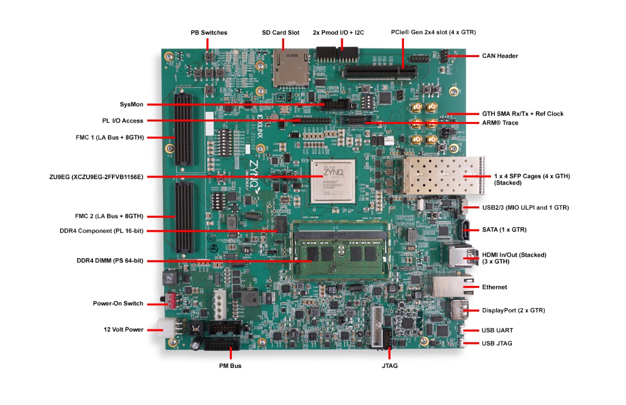
AMD Xilinx ZCU102 Rev 1.0 or later FPGA board and its power supply
EVAL-ADRV903x FMC evaluation board
SD card with at least 16GB of memory
Micro-USB cable (UART)
LAN cable (Ethernet)
(Optional) USB keyboard & mouse and a HDMI compatible monitor
More details as to why you need these, can be found at Prerequisites.
Testing
Creating the setup
Follow the steps in this order, to avoid damaging the components:
Connect the EVAL-ADRV903x FMC board to the ZCU102 HPC1 FMC1 socket
Insert SD card into the SD card socket on the FPGA
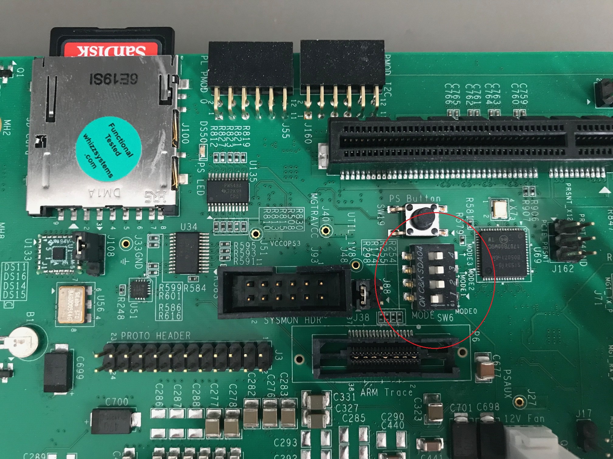
Configure ZCU102 for SD card boot mode (mode SW6[4:1] switch in the position OFF,OFF,OFF,ON as seen in the below picture)
Plug-in an Ethernet cable from your router/switch to the Ethernet port on the FPGA board
Connect USB UART J83 (Micro-USB) to your host PC
(Optional) Connect a monitor to the FPGA by HDMI, and a mouse and a keyboard
Turn on the power switch on the FPGA board
Observe Kernel and serial console output messages on your terminal (use the first ttyUSB or COM port registered)
Boot messages
The following is what is printed in the serial console, after you have connected to the proper ttyUSB or COM port:
Zynq MP First Stage Boot Loader
Release 2025.1   Dec  9 2025  -  14:14:37
NOTICE:  BL31: Non secure code at 0x8000000
NOTICE:  BL31: v2.12.0(release):xilinx-v2025.1
NOTICE:  BL31: Built : 11:08:56, Aug 12 2025
PMUFW:  v1.1


U-Boot 2018.01-21442-gf06dec3cab (Feb 13 2025 - 17:12:07 +0200) Xilinx ZynqMP ZCU102 revA

I2C:   ready
DRAM:  4 GiB
EL Level:       EL2
Chip ID:        zu9eg
MMC:   sdhci@ff170000: 0 (SD)
*** Warning - bad CRC, using default environment

In:    serial@ff000000
Out:   serial@ff000000
Err:   serial@ff000000
Bootmode: LVL_SHFT_SD_MODE1
Net:   ZYNQ GEM: ff0e0000, phyaddr 15, interface rgmii-id

Warning: ethernet@ff0e0000 using MAC address from ROM
eth0: ethernet@ff0e0000
Hit any key to stop autoboot:  0
switch to partitions #0, OK
mmc0 is current device
...
reading Image
44519936 bytes read in 2980 ms (14.2 MiB/s)
## Flattened Device Tree blob at 04000000
   Booting using the fdt blob at 0x4000000
   Loading Device Tree to 000000000fff0000, end 000000000ffff0f4 ... OK

Starting kernel ...

[    0.000000] Booting Linux on physical CPU 0x0000000000 [0x410fd034]
[    0.000000] Linux version 6.12.0-27064-g9495a3d76542 (spopa@HYB-JRXo5UEs61B) #16 SMP Tue Feb 17 17:01:10 EET 2026
[    0.000000] Machine model: ZynqMP ZCU102 Rev1.0
[    0.000000] earlycon: cdns0 at MMIO 0x00000000ff000000 (options '115200n8')
...
[    1.098167] jesd204: created con: id=6, topo=0, link=0, /fpga-axi@0/axi-jesd204-tx@84a90000 <-> /fpga-axi@0/axi-adrv903x-tx-hpc@84a04000
[    1.110365] jesd204: created con: id=7, topo=0, link=2, /fpga-axi@0/axi-jesd204-rx@84aa0000 <-> /axi/spi@ff040000/adrv903x-phy@0
[    1.121867] jesd204: created con: id=8, topo=0, link=3, /fpga-axi@0/axi-jesd204-rx-os@85aa0000 <-> /axi/spi@ff040000/adrv903x-phy@0
[    1.133633] jesd204: created con: id=9, topo=0, link=0, /fpga-axi@0/axi-adrv903x-tx-hpc@84a04000 <-> /axi/spi@ff040000/adrv903x-phy@0
[    1.145578] jesd204: /axi/spi@ff040000/adrv903x-phy@0: JESD204[0:0] transition uninitialized -> initialized
[    1.155254] jesd204: /axi/spi@ff040000/adrv903x-phy@0: JESD204[0:2] transition uninitialized -> initialized
[    1.164941] jesd204: /axi/spi@ff040000/adrv903x-phy@0: JESD204[0:3] transition uninitialized -> initialized
[    1.174630] jesd204: found 9 devices and 1 topologies
...
[    1.940648] axi_sysid 85000000.axi-sysid-0: [adrv903x] [JESD_MODE=64B66B ORX_ENABLE=1 RX:RATE=16.22 M=4 L=2 S=1 NP=16 TPL_WIDTH= LINKS=1 TX:RATE=16.22 M=4 L=2 S=1 NP=16 TPL_WIDTH= LINKS=1 ORX:RATE=16.22 M=4 L=2 S=1 NP=16 TPL_WIDTH= LINKS=1] on [zcu102]
...
[   29.767179] systemd[1]: Failed to look up module alias 'autofs4': Function not implemented
[   29.800681] systemd[1]: systemd 247.3-7+rpi1+deb11u2 running in system mode.

Welcome to Kuiper GNU/Linux 11.2 (bullseye)!

...
My IP address is 192.168.100.2 169.254.173.46

Raspbian GNU/Linux 11 analog ttyPS0

analog login:
Default login credentials:
Username:
analogPassword:
analog
Verifying the setup
After logging in, you can verify that the ADRV9032 device is properly detected by the Linux kernel:
~$
iio_info | grep iio:device
iio:device0: xilinx-ams
iio:device1: adrv903x-phy
iio:device2: axi-adrv903x-rx-hpc (buffer capable)
iio:device3: axi-adrv903x-tx-hpc (buffer capable)
Using no-OS as software
Necessary files
The following files are needed for the system to boot:
HDL boot file:
system_top.xsano-OS project: projects/adrv903x
Instructions on how to build the boot files from source can be found here:
projects/adrv903x. More no-OS build details at No-OS Build Guide.
projects/adrv9032. More HDL build details at Build an HDL project.
Required Software
AMD Xilinx Vivado and Vitis (downloading Vitis from here will include Vivado as well)
An UART terminal (Putty/Tera Term/Minicom, etc.), Baud rate 115200 (8N1)
Required Hardware
AMD Xilinx ZCU102 Rev 1.0 FPGA board and its power supply
EVAL-ADRV903x FMC evaluation board
2x Micro-USB cables, one for UART and one for JTAG
(Optional) USB keyboard & mouse and a HDMI-compatible monitor
More details as to why you need these, can be found at Prerequisites.