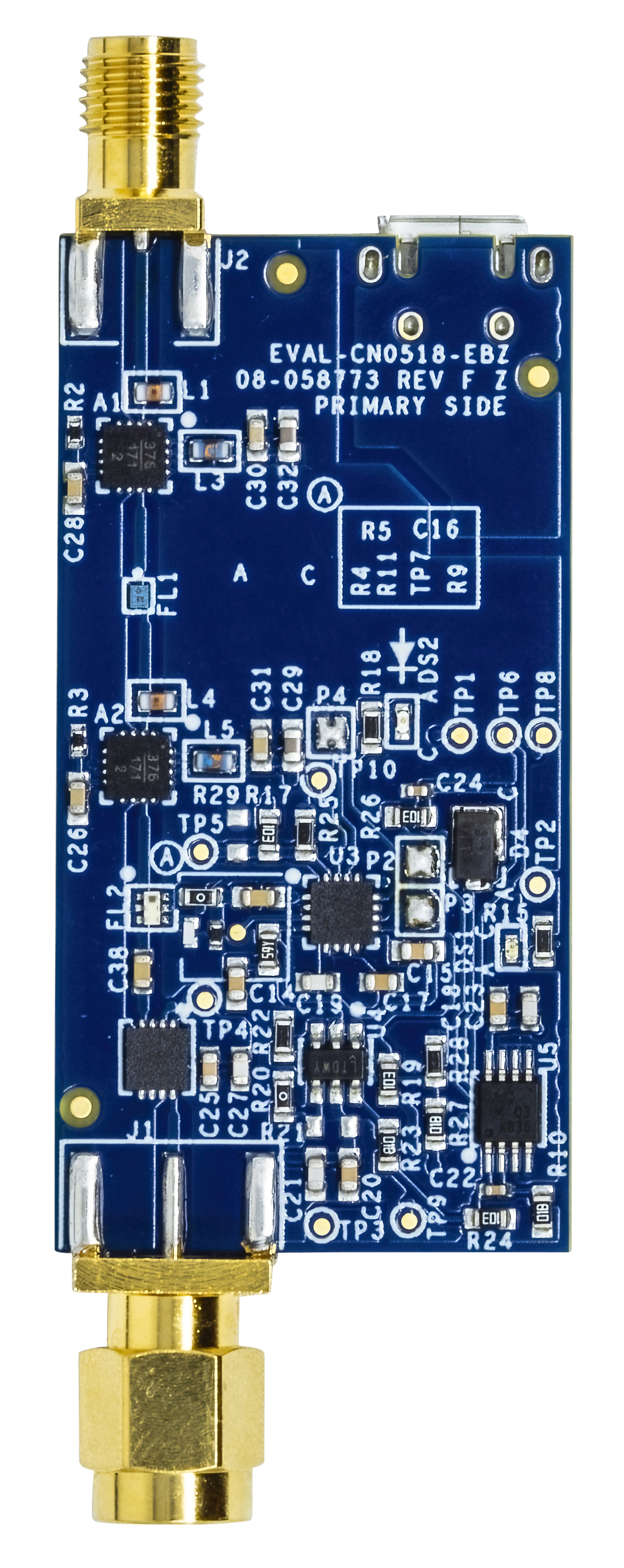
Primary Side
USB-Powered, 915 MHz RF Low Noise Amplifier Receiver with Overpower Protection Circuit.
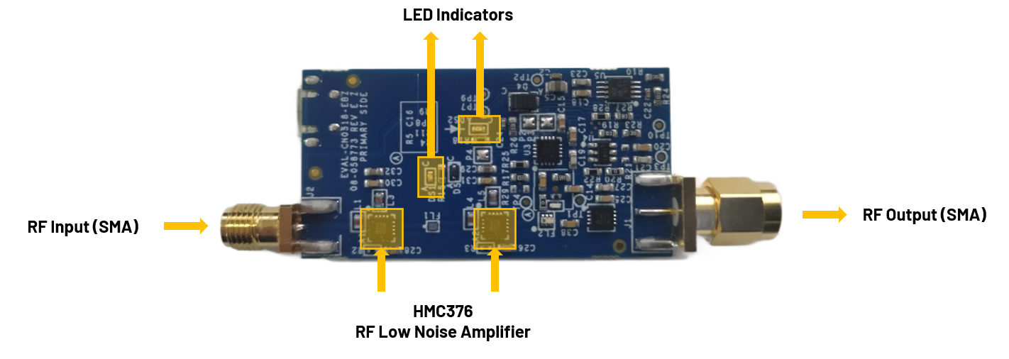
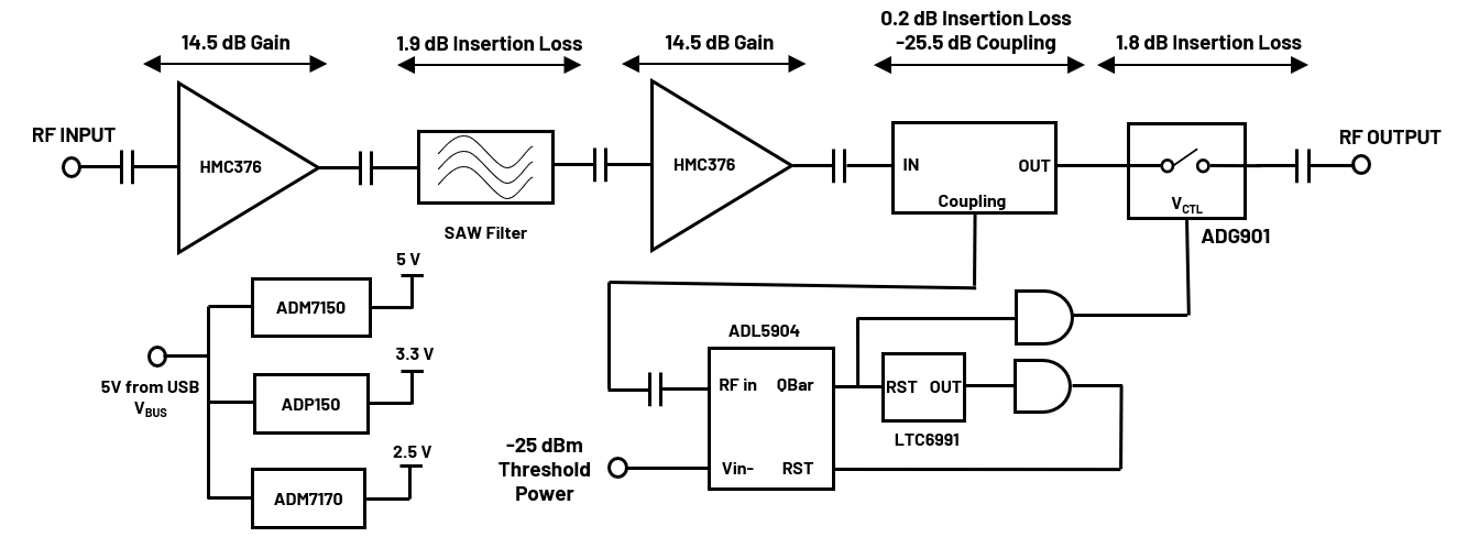
The EVAL-CN0518-EBZ is a USB-powered, RF power amplifier that is optimized for receiving signal chains in the 915 MHz ISM band. Using two HMC376 amplifiers cascaded together, the design provides a gain of 25dB and return losses of more than 10dB at its center frequency.
The circuit includes a high speed overpower cutoff that protects sensitive downstream equipment connected to the receiver system. The receiver system also automatically returns to normal operation when the RF power level drops within the acceptable range.
Designed to be used with the ADALM-PLUTO, the EVAL-CN0518-EBZ features a small form factor with dimensions of 25.4mm×49.6mmx1.5748mm (PCB only). The RF input and output are designed with a 50Ω impedance, enabling direct connection between the circuit and standard 50Ω systems.
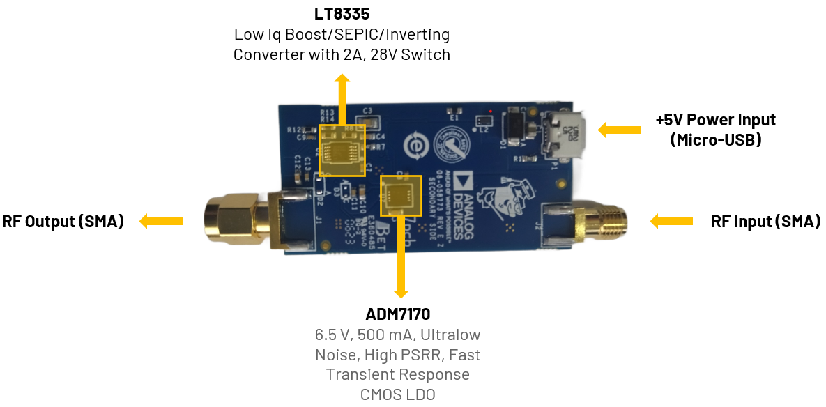
A micro-USB connector is used for the input power, allowing the evaluation board to use most 5V wall wart power supplies available in the market.
The EVAL-CN0518-EBZ features the HMC376, which is a GaAs, pHEMT, MMIC, low noise amplifier operating between 700MHz to 1000MHz. This amplifier is ideal for use in GSM and CDMA cellular base station front end receivers. This low noise amplifier does not require any external matching circuitry to operate.
The SMA connectors are used for the RF input and output connections.
RF Port |
Reference Designator |
Description |
RF Input (SMA male connector) |
J2 |
Connect to a radio or piece of RF equipment |
RF Output (SMA female connector) |
J1 |
Connect to an antenna |
The reference design uses two LEDs to indicate its current status:
RF Port |
Reference Designator |
Description |
|---|---|---|
Green LED |
DS1 |
Indicates that power is present on the board |
Red LED |
DS2 |
Indicates when an overpower event occurs |
This table shows the board status when the various LEDs are ON/OFF.
Green LED |
Red LED |
Board Status |
|---|---|---|
OFF |
OFF |
No Power |
ON |
OFF |
Normal RF Operation |
ON |
ON |
Overpower Event (RF Output Attenuated) |
P1 is the micro-USB port used to provide 5V power to the board.
Two (2) micro-USB power adaptor or micro-USB to USB cable for powering ADALM-PLUTO and EVAL-CN0518-EBZ
One (1) SMA male-to-male cable
For the step-by-step procedure on how to update the Pluto Firmware, you can use this user guide link.
The latest firmware version for the ADALM-PLUTO can be found here:
Download
ADALM-PLUTO Firmware: Pluto version latest release
Follow the step-by-step process on how to configure the ADALM-PLUTO for proper operation by referring to this link.
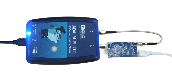
Connect directly the Rx port of ADALM-PLUTO to J1 of the EVAL-CN0518-EBZ.
Connect the Tx port of the ADALM-PLUTO to J2 of the EVAL-CN0518-EBZ using a male-to-male SMA cable.
Connect P1 (micro-USB) connector of the EVAL-CN0518-EBZ into a PC USB port or a 5V USB charger.
Connect the micro-USB to USB cable to a PC/laptop and the other end to the ADALM-PLUTO data port.
The DS2 LED of CN0518-EBZ will automatically turn on, indicating that the board is powered on and is in operation.
Important
The ADALM-PLUTO can be configured using an IIO Oscilloscope, visit the website on IIO Oscilloscope to learn more about the tool.
Important
Make sure to download or update to the latest version of IIO Oscilloscope found on this link.
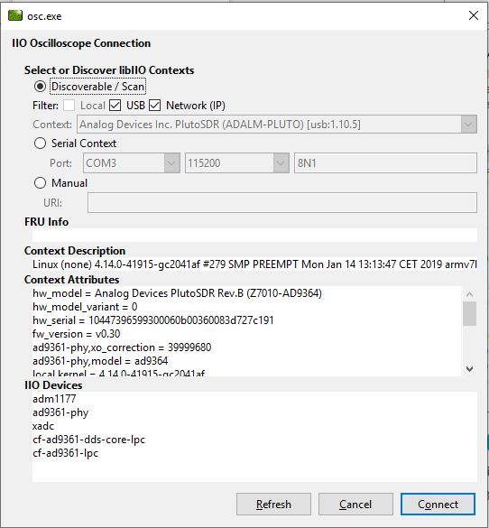
Once done with the installation or an update of the latest IIO Oscilloscope, open the application. The user needs to supply a URI, which will be used in the context creation of the IIO Oscilloscope. The instructions can be seen in the previous section.
Press refresh to display available IIO devices. Once the ADALM-PLUTO appeared, press connect.
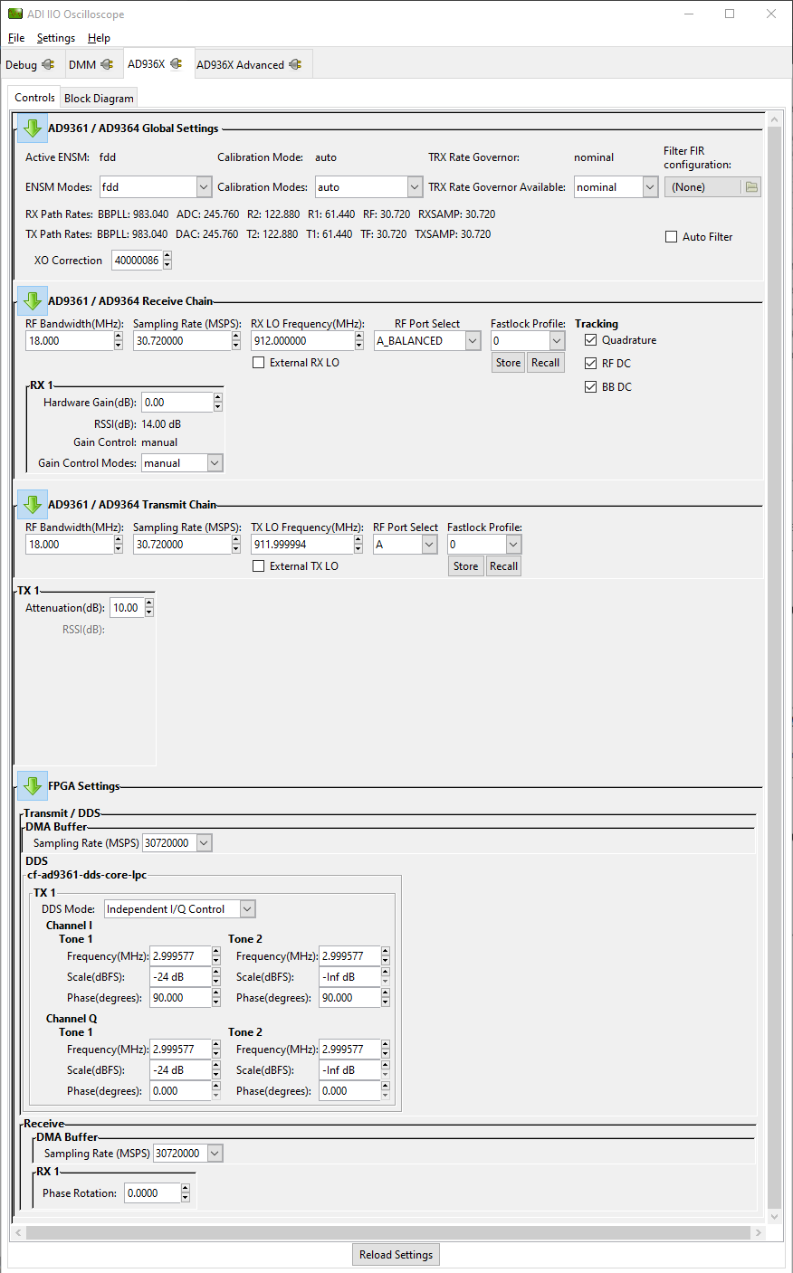
On the AD936x tab, set the required parameters for the EVAL-CN0518-EBZ to operate properly.
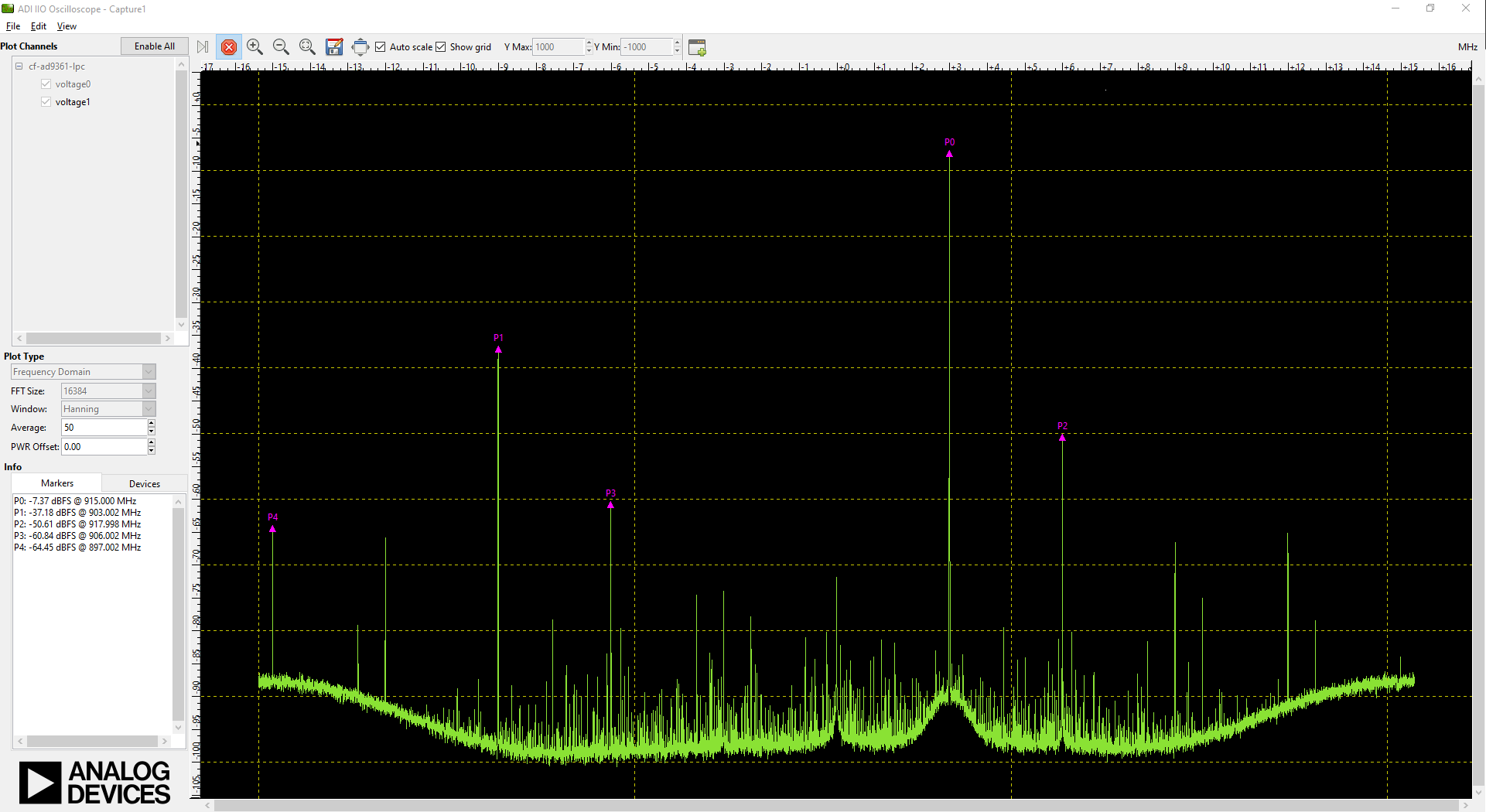
Using the capture window, you can see the RF output of the EVAL-CN0518-EBZ in the frequency domain.
Download
EVAL-CN0518-EBZ Design & Integration Files
Schematics
PCB Layout
Bill of Materials
Allegro Project
Tip
Receive software update notifications and documentation updates, view the latest videos, and more when you register your hardware. Register to receive all these great benefits and more!
For questions and more information about this product, connect with us through the Analog Devices EngineerZone .