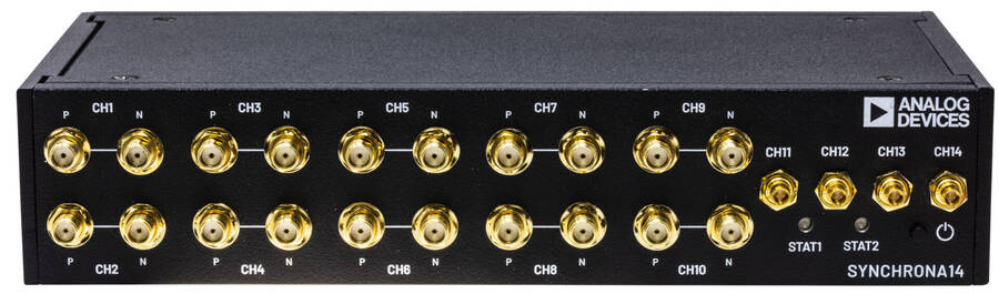
AD-SYNCHRONA14-EBZ
Multichannel System Clocking Device.
Overview
The AD-SYNCHRONA14-EBZ is an ideal self-contained device suitable for applications that require a highly accurate frequency and phase-controlled source clock. It is designed around the AD9545, a quad input synchronizer and jitter cleaner, and the HMC7044, a 3.2 GHz, 14-output high performance jitter attenuator. This board greatly simplifies clock distribution and multichannel synchronization in complex systems. Using popular industry connectors such as SMA and Samtec Circular RF Twinax, most labs have cables that are compatible with this device. It is intended for use in a lab environment by trained professionals for evaluation and prototyping purposes and can be used as a reference design for integrating into custom applications.
With its on-board internal oven-controlled crystal oscillator (OCXO), the AD-SYNCHRONA14-EBZ can operate in standalone mode or be fed from a choice of external sources such as three separate high speed differential clock inputs, a 10 MHz reference, and a 1 pps input. This flexibility, combined with the capability to select either of the internal voltage-controlled crystal oscillator (VCXO) options of 100 MHz or 122.88 MHz, gives almost unlimited choice for the frequency of interest and accuracy needed for a wide variety of application areas.
Applications
High accuracy reference clock distribution
Systems clocked from a single source
Use cases requiring 100 MHz or 122.88 MHz
Phased array systems, radar, EW, SATCOMS
Bench equipment
Remote controlled operation
Key Features
User Interfaces |
Gigabit Ethernet Male pin header (SPI & GPIO) USB Status LEDs |
Clock Inputs |
3 differential 100 Ω SMA clock inputs 1 pps input SYNC input 10 MHz input |
Clock Outputs |
4 x Twinax LVPECL ac/dc-coupled, 100 Ω 2 x SMA LVPECL ac-coupled 4 x SMA CMOS 4 x SMA LVDS ac-coupled Configurable differential outputs, 50 Ω diff |
Processing System |
Raspberry Pi 4, ARM Cortex-A72, 2 GB SDRAM |
Power Supply |
DC 12V, 3A barrel jack |
Internal References |
100 MHz and 122.88 MHz ultralow phase noise VCXOs (-165 dBc/Hz) 40 MHz and 38.4 MHz TCXOs (±1 ppm) 50 MHz OCXO (±10 ppb) Internal references are software configurable. |
Clock Processing Devices |
HMC7044 (High performance, 3.2 GHz, 14-output Jitter Attenuator) AD9545 (1 PPS Synchronizer and Adaptive Clock Translator) |
Hardware
Power Supply
Use a 12 Volts dc power supply with a minimum power of 36 W and a 2.1 x 5.5 mm barrel jack.
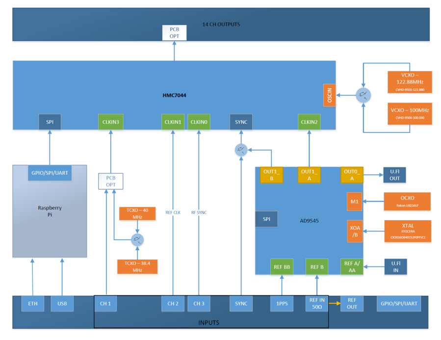
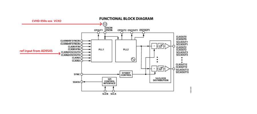
Block Diagram
Clock Output Configuration
There are a total of 14 high speed clocks that come out of the final clock mux; these can range from 2150 MHz to 3550 MHz in different modes and connection schemes. The maximum clock output is 2400 MHz, which can be divided down by 1, 2, 3, 4, 5, 6, and even numbers up to 4094. Moreover, the output clock resolution depends on the “Clock Distribution Frequency”, and the divider value.
The outputs are hardware configurable as LVPECL, LVDS, and CMOS.
Maximum Operating Frequency
LVPECL |
2400 MHz (3 dB bandwidth) |
LVDS |
1700 MHz |
CMOS |
600 MHz |
The table below shows the default configuration:
HMC7044 Pin Name |
Enclosure Designator |
Board Connector Designator |
Default Configuration |
|---|---|---|---|
CLKOUT0 |
CH11 |
P6 |
LVPECL AC-COUPLED |
CLKOUT1 |
CH12 |
P5 |
LVPECL AC-COUPLED |
CLKOUT2 |
CH14 |
P3 |
LVPECL DC-COUPLED |
CLKOUT3 |
CH13 |
P4 |
LVPECL DC-COUPLED |
CLKOUT4 |
CH8 |
J9 (P), J11 (N) |
CMOS |
CLKOUT5 |
CH10 |
J12 (P), J15 (N) |
LVPECL AC-COUPLED |
CLKOUT6 |
CH6 |
J13 (P), J16 (N) |
CMOS |
CLKOUT7 |
CH4 |
J10 (P), J14 (N) |
LVDS AC-COUPLED |
CLKOUT8 |
CH1 |
J17 (P), J18 (N) |
LVDS AC-COUPLED |
CLKOUT9 |
CH2 |
J19 (P), J20 (N) |
LVDS AC-COUPLED |
CLKOUT10 |
CH3 |
J1 (P), J2 (N) |
LVDS AC-COUPLED |
CLKOUT11 |
CH5 |
J3 (P), J4 (N) |
CMOS |
CLKOUT12 |
CH9 |
J5 (P), J7 (N) |
LVPECL AC-COUPLED |
CLKOUT13 |
CH7 |
J6 (P), J8 (N) |
CMOS |
The default configuration can be changed. Each channel has all the footprints for the passive components.
Example: CH2 - LVDS ac-coupled
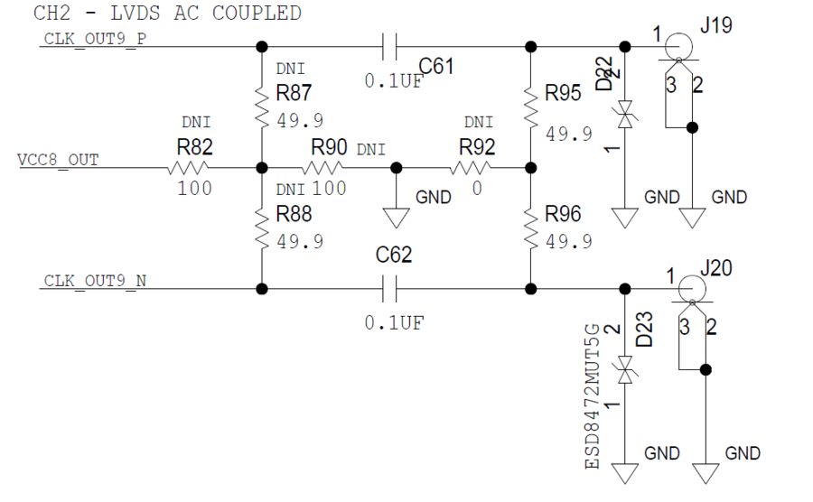
For LVDS ac-coupled |
Insert C61, C62 and R95, R96 for downstream devices with high impedance input. |
For LVPECL ac-coupled |
Insert C61, C62, R87, R88, R90, and then DNI the rest of the passive components. |
For LVPECL dc-coupled |
Replace C61 and C62 with 0 Ω resistors, insert R87, R88, R90, and then DNI the rest of the passive components. |
For CMOS |
Replace C61 and C62 with 0 Ω resistors, and then DNI the rest of the passive components. |
Check the HMC7044 data sheet (page 21) for more details on output configuration.
100 Ω Differential Connectors
CH11, CH12, CH13, and CH14 are 100 Ω impedance differential outputs with circular RF Twinax Jack.
The CJT-BH connector series from Samtec are paired with C28S connector series – Circular RF Twinax Cable Assembly.
Clock Input (Reference Input)
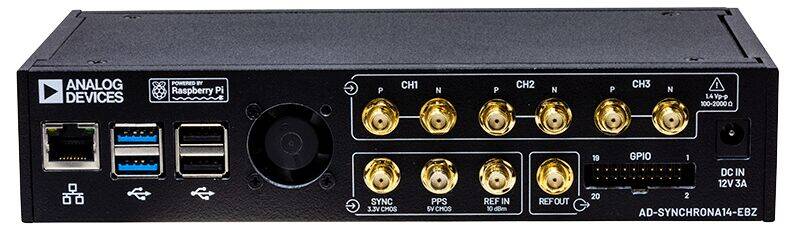
On the back panel, there are 3 differential 100 Ω inputs.
In the standard configuration, CH1 is disconnected from the SMA connectors. The reason for this is that inside the AD-SYNCHRONA14-EBZ, there are two temperature-compensated crystal oscillators (TCXOs) connected to this channel (38.4 MHz and 40 MHz). To use the SMA cables, insert C69 and C70, and remove C282 and C134.
CH2 goes directly into HMC7044 and it is ac-coupled. |
CH3 goes directly into HMC7044 and it is dc-coupled. |
PPS is a CMOS input for 1 pps reference. The range for this input is from 1.8 V to 5 V. |
SYNC is a 3.3 V CMOS input that goes directly into HMC7044 sync pin. |
REF_IN is a 50 Ω input with a maximum input power of 10 dBm. With the standard software version, this input is set to function with a 10 MHz reference. The maximum input frequency is 160 MHz (–3dB). |
REF_OUT is a CMOS output of the REF_IN buffer. |
Internal References
There are two VCXOs, ultralow phase noise oscillators (-165dBc/Hz).
The VCXOs are 100 MHz and 122.88 MHz; both of which are software selectable and used to drive the PLL2 of HMC7044.
There are also two TCXOs (±1 ppm), 40 MHz and 38.4 MHz that can be used as reference for PLL1 of HMC7044.
Switching between VCXOs goes together with switching the TCXOs; 100 MHz with 40 MHz, and 122.88 MHz with 38.4 MHz.
The AD9545 has a 50 MHz OCXO (±10 ppb) reference, so AD-SYNCHRONA14-EBZ can be used as a standalone device, providing high frequency stability.
Software
Drivers
GUI
The Raspberry Pi inside AD-SYNCHRONA14-EBZ runs the RaspAP, which is an application that gives access to the GUI.
To access the GUI, the user must first get the IP of the device.
In the default configuration, AD-SYNCHRONA14-EBZ has the IP set as static 192.168.2.1
Note
Make sure that you are using an IP in the same class on your PC.
To find the IP of the SYNCHRONA:
Connect the add-on board that you received along with the AD-SYNCHRONA14-EBZ, in the back to the GPIO port
Make sure Enable jumper P4 is not connected
Connect an USB cable from it to your PC
Power on SYNCHRONA
Open a terminal (i.e. PuTTY)
Select the COM and 115200 baud rate
Wait a few seconds then hit any key to see if it booted already
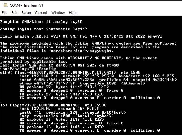
Type ifconfig. This should look like this:
Raspbian GNU/Linux 11 analog ttyS0

analog login: root (automatic login)

Linux analog 5.10.63-v7l+ #1 SMP Fri May 6 11:30:22 UTC 2022 armv7l

The programs included with the Debian GNU/Linux system are free
software; the exact distribution terms for each program are described
in the individual files in /usr/share/doc/\*/copyright.

Debian GNU/Linux comes with ABSOLUTELY NO WARRANTY, to the extent
permitted by applicable law.

Last login: Sun Jun 12 04:05:54 BST 2022 on ttyS0
~$
ifconfig
eth0: flags=4163<UP,BROADCAST,RUNNING,MULTICAST> mtu 1500
   inet 192.168.2.1 netmask 255.255.255.0 broadcast 192.168.2.255
   inet6 fe80::6b61:ce03:6067:283c prefixlen 64 scopeid 0x20
   ether e4:5f:01:93:77:3f txqueuelen 1000 (Ethernet)
   RX packets 79 bytes 11147 (10.8 KiB)
   RX errors 0 dropped 0 overruns 0 frame 0
   TX packets 29 bytes 5447 (5.3 KiB)*
   TX errors 0 dropped 0 overruns 0 carrier 0 collisions 0
lo: flags=73<UP,LOOPBACK,RUNNING> mtu 65536*
   inet 127.0.0.1 netmask 255.0.0.0
   inet6 ::1 prefixlen 128 scopeid 0x10<host>
   loop txqueuelen 1000 (Local Loopback)*
   RX packets 16 bytes 1188 (1.1 KiB)*
   RX errors 0 dropped 0 overruns 0 frame 0*
   TX packets 16 bytes 1188 (1.1 KiB)
   TX errors 0 dropped 0 overruns 0 carrier 0 collisions 0
Now you need to enable DHCP on SYNCHRONA. You need to do the followings:
~$
cd /linux_image_ADI-scripts/
/linux_image_ADI-scripts$
./enable_dhcp.sh
/linux_image_ADI-scripts$
reboot
Wait for the device to reboot. When all is done, you should see the initial text like in the code snippet from above
Now, typing ifconfig should give you a different address from the default one which was inet 192.168.2.1
Type the IP in your browser to access the GUI. The default username is admin and the password is analog.
General Page
The General Page of the GUI allows users to enable/disable channels, and set the frequencies on each channel. Refer to the Clock Output Configuration section above for the proper settings.
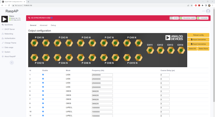
There are two VCXOs inside the AD-SYNCHRONA14-EBZ. Based on the frequencies you set in the General Page, the switch between the two VCXOs will be done automatically and the PLL frequency will be calculated.
Important
The values on each channel need to be submultiples of the PLL frequency.
If one or more of the values cannot be obtained from dividing the PLL frequency, the GUI will return the message:
Invalid Frequencies: Cannot solve HMC7044 clock configuration…
To apply the settings you made, click on the Reload Config button.
Coarse delay is another feature you can find in the General Page. Coarse delay can be set in step that are calculated based on the VCO frequency. Use the arrows in the coarse delay field to modify the coarse delay. The value is set in picoseconds. This feature can be used to compensate for unmatched RF cables.

In the General Page, users can see three status icons (left to right):
The first icon indicates the reference that AD-SYNCHRONA14-EBZ is using;
The second icon indicates if the devicetree is loaded; and
The third icon indicates if the device is connected.
To know the updated status, click on the status icons, as shown below.
In the General Page, you also have access to importing and exporting a devicetree with your settings.
When importing a devicetree, make sure that the name of the file is rpi-ad9545-hmc7044.dtbo
After importing a devicetree, click on Reload Config to apply the settings.
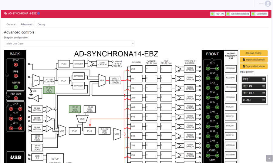
Advanced Page
In the Advanced Page of the GUI, you can find a detailed block diagram of AD-SYNCHRONA14-EBZ.
As shown in the illustration below, you can see the VCXO that is being used (highlighted in green). Also, the valid inputs on the left side are highlighted in green. In this case, a 10 MHz reference is connected into REF_IN.
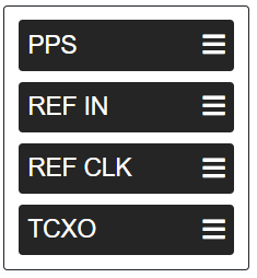
Input Priority
The input priority table is used to prioritize the input references.
Set the input priority table by dragging each reference upwards or downwards, as shown in the figure below:
Click on Reload Config to apply the changes.
If one of the references is invalid, AD-SYNCHRONA14-EBZ will jump automatically to the next valid reference.
Coarse Delay & Fine Delay
Coarse delay and fine delay settings are also available in the Advanced Page.
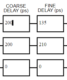
Use the arrows to set the coarse and the fine delay.
Click on Reload Config to apply the changes.
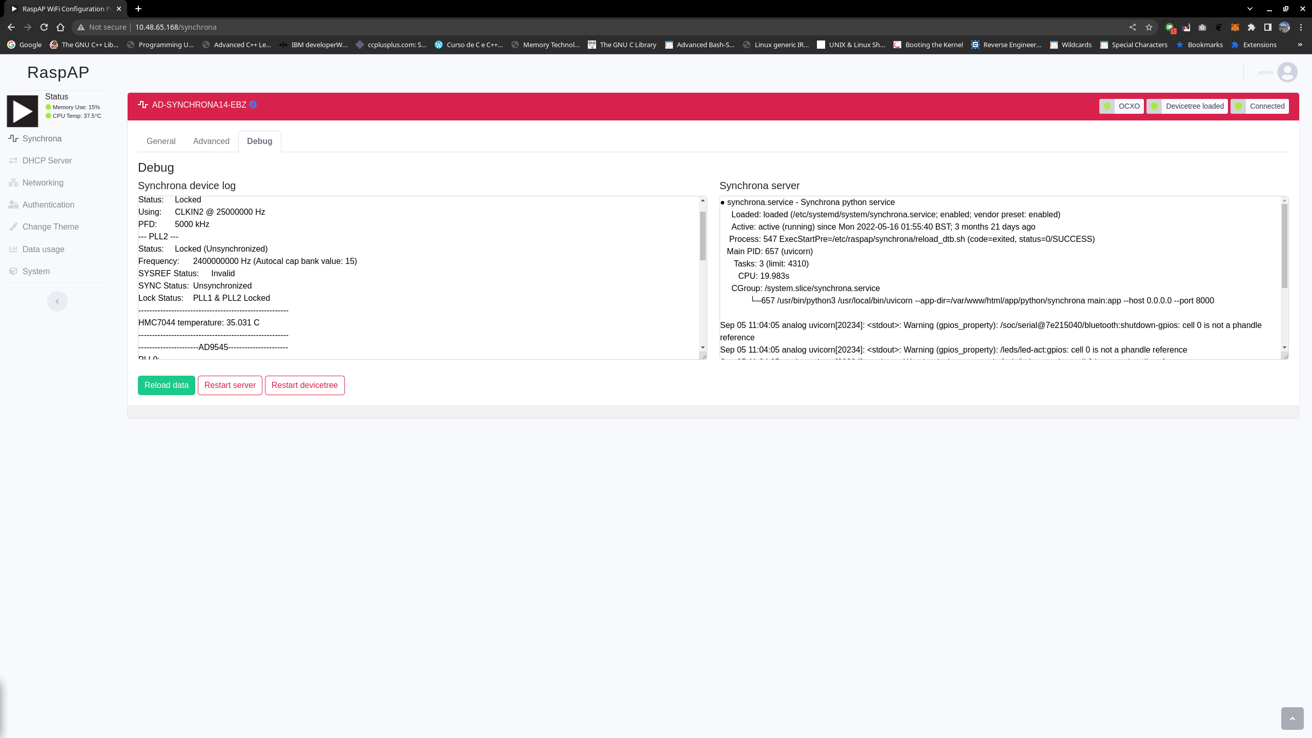
Debug Page
This page features various debug information. On top of this, more actions are available for users’ access, as shown in the illustration below:
Features Available in Debug Page |
Function |
|---|---|
Synchrona device log |
This panel presents various information about the clock chips, including a special note for the lock status of the various PLLs, which can be handy in ensuring that the input reference status displayed in the status LED is coherent. This information, together with the Input Priority list (displayed in the advanced page), is also useful to make sure the expected reference is, in fact, being used. |
Synchrona server |
This panel displays the status of the Synchrona server running on the device. |
Restart server |
This button restarts the Synchrona server. |
Restart devicetree |
This button basically brings the device to its default configuration after installation. |
Reload data |
This button reloads all debug logs and configurations into the GUI. Note that this function does not change device configuration. |
Use Cases
Standalone Use Case
The AD-SYNCHRONA14-EBZ can be used as a standalone device without the need of an external clock reference.
Inside the AD-SYNCHRONA14-EBZ, there is a Raspberry Pi connected to all the clock ICs that run all the drivers.
In the standalone use case, the main clock reference is the 50 MHz OCXO (Rakon U8216LF) that feeds the AD9545 clock IC. The 50 MHz OCXO used in this design has a frequency stability over temperature of ±10 ppb, and a warm up time of about 60 seconds for the reference frequency to be within ±20 ppb.
The AD9545 can provide any clock frequency up to 500 MHz. The differential output OUT1_A of the AD9545 is connected directly (ac-coupled) to PLL1 reference input (CLKIN2) of HMC7044. The reference input to PLL2 of HMC7044 is connected via an RF switch to two ultralow phase noise VCXOs.
The AD-SYNCHRONA14-EBZ also includes 100 MHz and 122.88 MHz VCXOs, making it capable to provide frequencies for instrumentation and telecom applications. Depending on the type of application and range of frequencies you want to use, the firmware will automatically switch between the VCXOs and change the output frequency of AD9545.
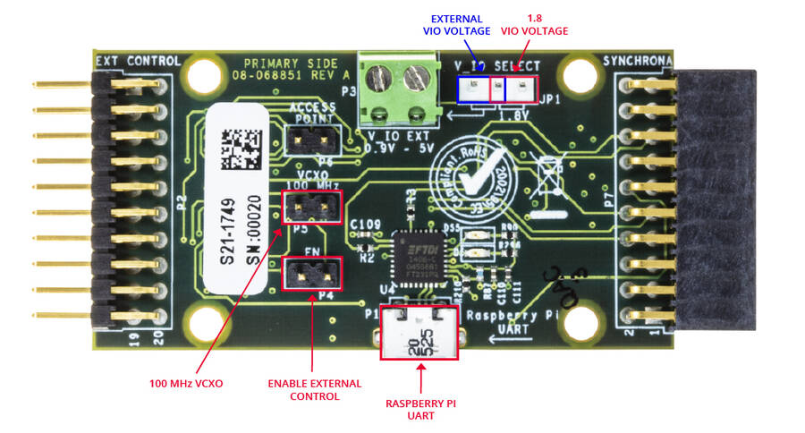
ADD-ON Voltage Translation Board
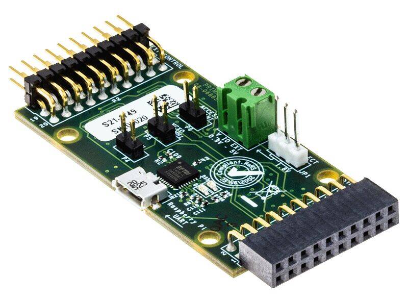
Inside the AD-SYNCHRONA14-EBZ package, you can find an ADD-ON board that allows you to connect via SPI with an external CPU or FPGA. It has voltage translators able to function from 0.9 V to 5 V. It also gives access to the Raspberry Pi UART via USB.
When the EN jumper (enable) is placed, the SPI interface is disconnected from the Raspberry Pi inside, allowing external SPI control.
The VIO_SELECT allows the user to select V_IO voltage of 1.8 V (on-board) or the external V_IO voltage connected on P3.
The VCXO 100 MHz jumper forces the use of the 100 MHz VCXO inside AD-SYNCHRONA14-EBZ.
Design and Integration Files
User Guides
The following user guides are available: