EVAL-AD5592R-PMDZ
8-channel, 12-Bit, Configurable ADC/DAC/GPIO with on-chip Reference, SPI Interface Pmod Module.
Overview
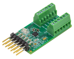
The EVAL-AD5592R-PMDZ is a minimalist 8-channel, 12-Bit, configurable ADC/DAC/GPIO with on-chip reference, SPI interface Pmod module. This board serves as a low-cost alternative to the full-featured product evaluation boards, with terminal block connections and no extra signal conditioning.
This user guide will focus on the hardware aspect of the EVAL-AD5592R-PMDZ including the connectors, indicators, and different configurations a user would require in order to use the hardware. There is also a link to the design files as well as software reference designs that use the hardware with example embedded firmware for a real demo.
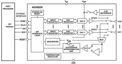
Simplified functional block diagram
Connectors and Configuration
The following section reviews all the hardware connectors and how to interface with them. It also reviews configuration options and well as important onboard indicators.
Analog/Digital I/O Connector (P2 & P3)
Connector |
Pin No. |
Pin Name |
Pin Description |
|---|---|---|---|
P3 |
1 2 3 4 5 6 |
CH3 CH2 CH1 CH0 GND VDD |
Channel 3 Input/Output Channel 2 Input/Output Channel 1 Input/Output Channel 0 Input/Output Ground Power Supply |
P2 |
1 2 3 4 5 6 |
VREF GND CH7 CH6 CH5 CH4 |
Voltage Reference Ground Channel 7 Input/Output Channel 6 Input/Output Channel 5 Input/Output Channel 4 Input/Output |
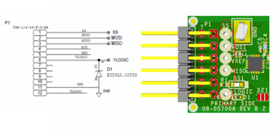
SPI Pmod Connector (P1)
Connector |
Pin No. |
Pin Name |
ADuCM3029 Pin Function |
ADuCM3029 Port No. |
|---|---|---|---|---|
SPI_PMOD |
1 |
CS |
SPI1_CS0/GPIO25 |
P1_09 |
2 |
MOSI |
SPI1_MOSI/GPIO23 |
P1_07 |
|
3 |
MISO |
SPI1_MISO/GPIO24 |
P1_08 |
|
4 |
SCLK |
SPI1_SCLK/GPIO22 |
P1_06 |
|
5 |
DGND |
DGND |
||
6 |
3.3V |
+3.3V |
||
7 |
IO16 |
XINT1_WAKE2/GPIO16 |
P1_00 |
|
8 |
RESET |
SYS_HWRST_N |
||
9 |
RDY |
SPI1_RDY/TMR0_OUT/GPIO14 |
P0_14 |
|
10 |
IO12 |
SPT0_AD0/GPIO12 |
P0_12 |
|
11 |
DGND |
DGND |
||
12 |
3.3V |
+3.3V |
||
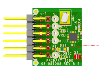
Test Points
Users can also check the SPI signal quality, supply, and reference voltage of the board using test points labeled SS, MOSI, MISO, VLOGIC, and VREF
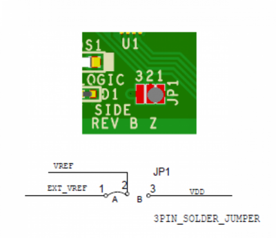
Voltage reference configuration
The default connection of the AD5592R VREF pin is shorted at pin 1 of JP1 solder jumper where you can easily configure your voltage reference input at pin 1 of terminal block P2, either from an external source or internal 2.5 V.
LED Indicator
The DS1 is the power green LED indicator of the board.
Power Supply Considerations and Configuration
When using the AD5592R Pmod board, the 3.3 V power for the Pmod comes directly from the host board it is connected to. The power from the host is generally capable of providing up to 100 mA at 3.3 V, but for complete Pmod power specifications, please click here.
Device Driver Support
There are two device driver solutions that are provided for controlling the EVAL-AD5592R-PMDZ:
AD5592R no-OS Driver
The AD5592R no-OS driver is used in bare-metal applications, typically running on low-power, embedded microcontrollers.
AD5592R Linux Driver
The AD5592R is used in applications running the Linux operating system, typically on larger processors and SoC devices.
The AD5592R Linux driver uses the Industrial Input/Output (IIO) framework, greatly simplifying the development of application code via the cross-platform Libiio library, which is written in C and includes bindings for Python, MATLAB, C#, and other languages. Application code can run directly on the platform board, communicating with the device over the local backend, or from a remote host over the network or USB backends.
System Setup Using ADICUP3029
The EVAL-AD5592R-PMDZ can be used with ADICUP3029.
Demo Requirements
The following is the list of items needed in order to replicate this demo.
Hardware
Micro-USB to USB Cable
PC or Laptop with USB Port
Software
PuTTY or other similar software
Important
There are two basic ways to program the ADICUP3029 with the software for the AD5592R.
Dragging and Dropping the Hex to the DAPLink drive
Using the drag and drop method, the software is going to be a version that Analog Devices creates for testing and evaluation purposes. This is the EASIEST way to get started with the reference design.
Building, Compiling, and Debugging using CCES
Importing the project into CrossCore Embedded Studio is going to allow you to change parameters and customize the software to your application, but will a bit more advanced and will require you to download the CrossCore toolchain.
Download
The software for the ADICUP3029_AD5592R demo can be found here:
Prebuilt AD5592R Hex File
Complete AD5592R Source Files
Setting up the Hardware
Connect the EVAL-AD5592R-PMDZ board at connector P8 of the EVAL-ADICUP3029.
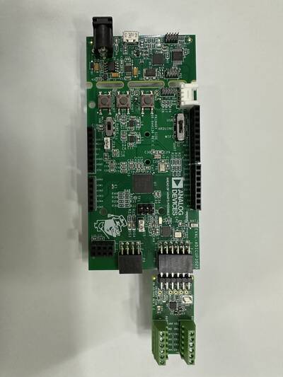
Figure 6 EVAL-AD5592R-PMDZ Connected to EVAL-ADICUP3029 at P8
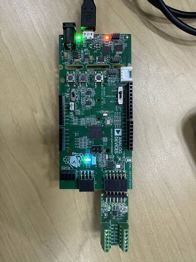
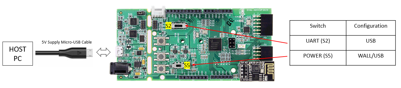
Connect a micro-USB cable to the P8 connector of the EVAL-ADICUP3029 and connect it to a computer. The final setup should look similar to the picture below.
Make sure the following switches are as shown in the table below.
From your PC, open My Computer and look for the DAPLINK drive, if you see this then the drivers are complete and correct.
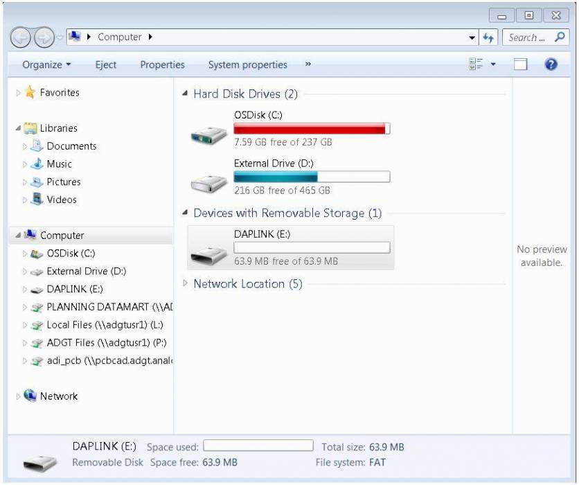
Simply extract the provided zip file. Once extracted, you will see the pre-built hex file for the AD5592R demo. Then drag and drop this Hex file to the DAPLINK drive and your ADICUP3029 board will be programmed. The DS2 (red) LED will blink rapidly.
The DS2 will stop blinking and will stay ON once the programming is done.
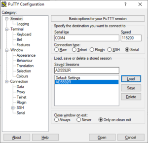
Open PuTTY or other similar software. Check the Device Manager to set the correct COM port for the ADICUP3029. Set the baud rate to 115200.
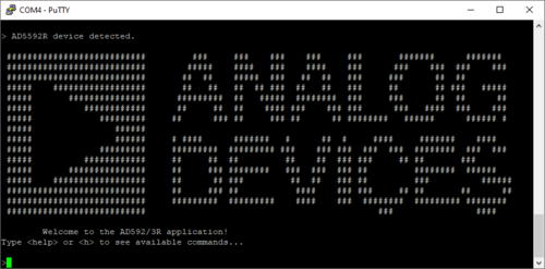
The expected output viewed in the PuTTY is shown below.
System Setup Using Raspberry Pi
The EVAL-AD5592R-PMDZ can be used with a Raspberry Pi.
Demo Requirements
The following is a list of items needed in order to replicate this demo.
Hardware
Raspberry PI Zero, Zero W, 3B+, or 4
16GB (or larger) Class 10 (or faster) micro-SD card
5Vdc, 2.5A power supply with micro USB connector (USB-C power supply for Raspberry Pi 4)
User interface setup (choose one):
HDMI monitor, keyboard, and mouse plugged directly into Raspberry Pi
Host Windows/Linux/Mac computer on the same network as Raspberry Pi
Software
Loading Image on SD Card
In order to boot the Raspberry Pi and control the EVAL-AD5592R-PMDZ, you will need to install ADI Kuiper Linux on an SD card. Complete instructions, including where to download the SD card image, how to write it to the SD card, and how to configure the system are provided on the Kuiper Linux Image
Configuring the SD Card
Follow the configuration procedure under Configuring the SD Card for Raspberry Pi Projects on the Kuiper Linux Image page, substituting the following lines in config.txt:
dtoverlay=rpi-ad5592r
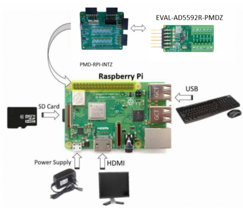
Setting up the Hardware
To set up the circuit for evaluation, consider the following steps:
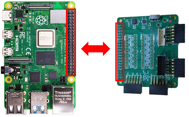
Connect the P9 of the PMOD to Raspberry Pi Interposer board at the male header GPIO pin connector of the Raspberry Pi as shown below.
Connect the EVAL-AD5592R-PMDZ on the PMOD to Raspberry Pi Interposer board either via Port P1 or P2.
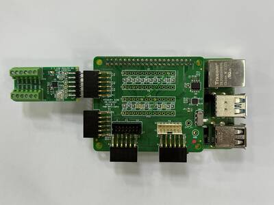
Figure 13 EVAL-AD5592R-PMDZ Connected to Raspberry Pi via Interposer
Burn the SD card with the proper ADI Kuiper Linux image. Insert the burned SD card into the designated slot on the RPi.
Connect the system to a monitor using an HDMI cable through the mini HDMI connector on the RPi.
Connect a USB keyboard and mouse to the RPi through the USB ports.
Power on the RPi board by plugging in a 5V power supply with a micro-USB connector. The final setup should look similar to the picture below.
Application Software (All Platforms)
Hardware Connection
The Libiio is a library used for interfacing with IIO devices and is required to be installed on your computer.
Download
Download and Install the latest Libiio package on your machine.
To be able to connect your device, the software must be able to create a context. The context creation in the software depends on the backend used to connect to the device as well as the platform where the EVAL-AD5592R-PMDZ is attached. Two platforms are currently supported for the AD5592R: Raspberry Pi using the ADI Kuiper Linux and the ADICUP3029 running the no-OS AD5592R demo project. The user needs to supply a URI which will be used in the context creation.
The iio_info command is a part of the libIIO package that reports all IIO attributes.
Upon installation, simply enter the command on the terminal command line to access it.
For RPI Direct Local Access:
iio_info
For Windows machine connected to Raspberry Pi:
iio_info -u ip:<ip address of your ip>
Example:
If your Raspberry Pi has the IP address 192.168.1.7, you have to use iio_info -u ip::192.168.1.7 as your URI
Note
Do note that the Windows machine and the RPI board should be connected to the same network in order for the machine to detect the device.
IIO Commands
There are different commands that can be used to manage and control the device being used. The iio_attr command reads and writes IIO attributes.
analog@analog:~$ iio_attr [OPTION]...
Example:
To look at the context attributes, enter this code on the terminal:
analog@analog:~$ iio_attr -a -C
The iio_reg command reads or writes SPI or I2C registers in an IIO device. This is generally not needed for end applications but can be useful in debugging drivers. Note that you need to specify a context using the -u qualifier when you are not directly accessing the device via RPI or when you are using the ADICUP3029 platform.
analog@analog:~$ iio_reg -u <context> <device> <register> [<value>]
Example:
To read the device ID (register = 0x02) of an AD5592R interfaced via RPI from a Windows machine, enter the following code on the terminal:
iio_reg -u ip: ad5592r 0x02
IIO Oscilloscope
Caution
Make sure to download/update to the latest version of IIO-Oscilloscope found on this link
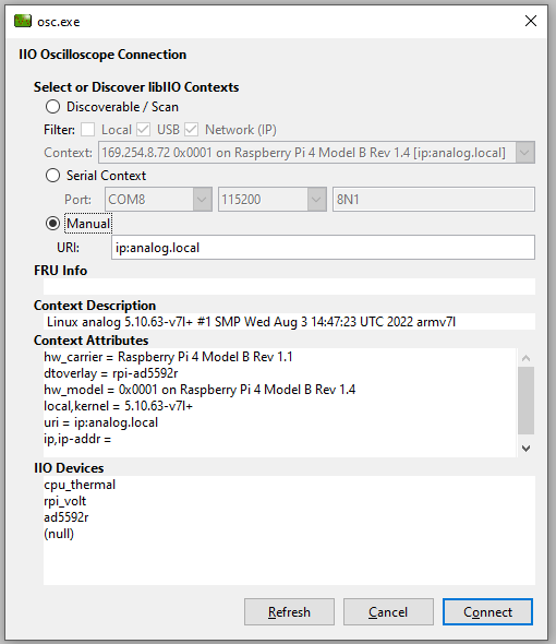
Once done with the installation or an update of the latest IIO-Oscilloscope, open the application. The user needs to supply a URI which will be used in the context creation of the IIO Oscilloscope and the instructions can be seen in the previous section.
Press refresh to display available IIO Devices, once ad5592r appeared, press connect.
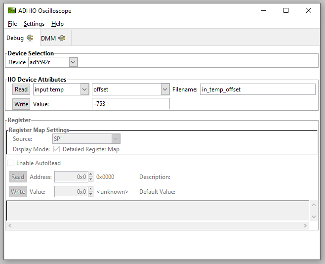
Debug Panel
Below is the Debug panel of AD5592R wherein you can directly access the attributes of the device.
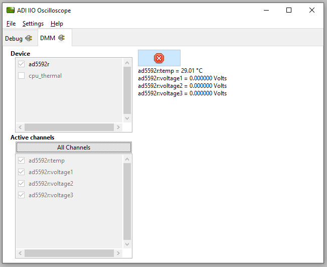
DMM Panel
Access the DMM panel to see the instantaneous reading of the device temperature and voltages.
PyADI-IIO
PyADI-IIO is a Python abstraction module for ADI hardware with IIO drivers to make them easier to use. This module provides device-specific APIs built on top of the current libIIO Python bindings. These interfaces try to match the driver naming as much as possible without the need to understand the complexities of libIIO and IIO.
Follow the step-by-step procedure on how to install, configure, and set up PyADI-IIO and install the necessary packages/modules needed by referring to the PyADI-IIO documentation.
Running the example
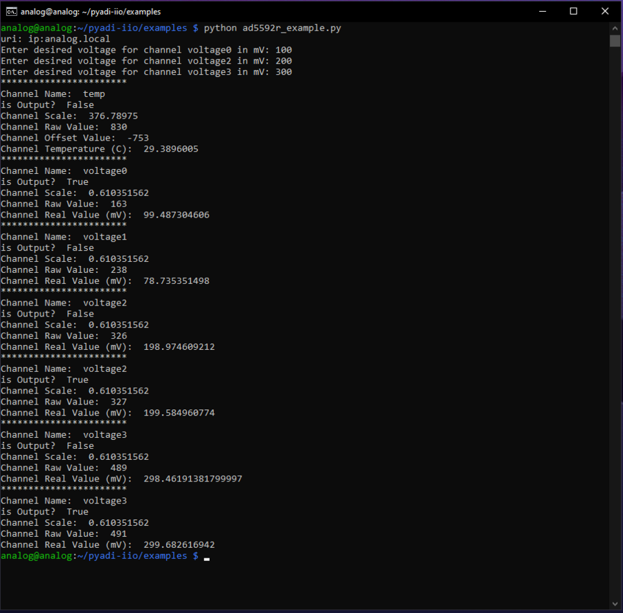
After installing and configuring PYADI-IIO in your machine, you are now ready to run Python script examples. In our case, run the ad5592r_example.py found in the examples folder.
D:\pyadi-iio\examples>python ad5592r_example.py
Press enter. Input desired voltage levels and you will get these readings.
Download
Github link for the Python sample script: AD5592R Python Example
More Information and Useful Links
Schematic, PCB Layout, Bill of Materials
Download
EVAL-AD5592R-PMDZ Design & Integration Files
Schematics
PCB Layout
Bill of Materials
Allegro Project
Additional Information
Registration
Receive software update notifications, documentation updates, view the latest videos, and more when you register your hardware. Register to receive all these great benefits and more!