User guide
The complete user guide of the evaluation board can be found at CN0540 Reference Design.
Hardware guide
General Setup
Jumper Placement
The EVAL-CN0540-ARDZ Shield (CN0540 Board) includes a jumper that the user should be sure is placed in the correct position on P10. This jumper connects the current source to the circuit and may be removed for testing without a current source.
Sensor Input
The main input on the EVAL-CN0540-ARDZ is a right-angle SMA connector on the front of the board, as such it is highly recommended to connect the sensor using an SMA cable. If this is not possible, due to the type of sensor or otherwise, there is also the header P1 which can be connected to with standard wires. The software detailed below has an option to compensate for the voltage offset caused by a connected sensor which should always be run after connecting a new sensor.
LED Indicators
On the EVAL-CN0540-ARDZ board there are four LED lights. The PWR LED in the bottom-left corner indicates if the board is currently powered. LED1 and the CC LED, located in the top-right corner, indicate that the board is connected through the Arduino connectors. The FAULT LED is located just below them and indicates whether or not the switch’s fault flag is raised.
Arduino Interface
All connector pinouts for the EVAL-CN0540-ARDZ are described in the table below.
Connector |
Pin No. |
Pin Name |
CN0540 Pin Function |
|---|---|---|---|
Arduino DIO High |
1 |
SCL |
SCL |
Arduino DIO High |
2 |
SDA |
SDA |
Arduino DIO High |
3 |
AREF |
NC (Not connected) |
Arduino DIO High |
4 |
AGND |
DGND |
Arduino DIO High |
5 |
SCLK |
SCLK |
Arduino DIO High |
6 |
MISO |
DOUT_RDYB |
Arduino DIO High |
7 |
MOSI |
SDI |
Arduino DIO High |
8 |
CS |
CS_ADC |
Arduino DIO High |
9 |
RDY |
SHUTDOWN |
Arduino DIO High |
10 |
IO28 |
NC |
Arduino DIO Low |
1 |
IO08 |
RESET_ADC |
Arduino DIO Low |
2 |
IO27 |
SYNC_IN |
Arduino DIO Low |
3 |
IO33 |
CSB_AUX |
Arduino DIO Low |
4 |
IO09 |
SW_FF |
Arduino DIO Low |
5 |
IO13 |
DRDY_AUX |
Arduino DIO Low |
6 |
IO15 |
DRDY |
Arduino DIO Low |
7 |
TX |
LED1 |
Arduino DIO Low |
8 |
RX |
LED2 |
Arduino Analog |
1 |
AIN0 |
IO5 |
Arduino Analog |
2 |
AIN1 |
IO4 |
Arduino Analog |
3 |
AIN2 |
IO3 |
Arduino Analog |
4 |
AIN3 |
NC |
Arduino Analog |
5 |
AIN4 |
NC |
Arduino Analog |
6 |
AIN5 |
IO0 |
Arduino Power |
1 |
NC |
NC |
Arduino Power |
2 |
IOREF |
IOREF |
Arduino Power |
3 |
RESET |
NC |
Arduino Power |
4 |
3.3V |
3V3 |
Arduino Power |
5 |
5V |
NC |
Arduino Power |
6 |
GND |
GND |
Arduino Power |
7 |
GND |
GND |
Arduino Power |
8 |
Vin |
NC |
Piezo Accelerometer Sensor Results
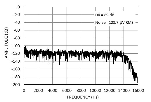
To achieve reasonable noise measurements, the piezo accelerometer must be either stabilized using an active shaker table which cancels environmental vibrations or anchored to a massive object which makes sensor still. Anchoring to a massive object was used for a following measurements, where the piezo accelerometer was connected directly to the input of the signal chain.
The following figures show DC and AC coupled solution comparison, where the DC coupled version is producing more noise, but it is more linear. Whereas the AC coupled is nonlinear at very low frequencies (a spike near DC frequency bin), caused by a coupling capacitor.
(Optional) Hardware Interface
The board includes many ways in its hardware to interface with the components. These are optional interfaces that can be used to externally control aspects of the components.
Connector |
Description |
|---|---|
P7 |
Externally control the shift voltage, used in the piezo sensor bias voltage correction. |
J2 & J3 |
Allows the user to input voltage while bypassing the front‑end, directly into the ADC driver. |
J4 |
Externally provide the MCLK. |
P6 |
Allows the user to use I2C protocol to provide the voltage supply, the SCL and SDA. |
P8 |
PMOD connector allows the user to interface with the board without Arduino. |
P9 |
Allows the user to connect a digital MEMS microphone and interact with it using the Arduino connectors. |
Test Points
The board also has many test points, most of which are labelled and are fairly self-explanatory. The table below describes some of the most significant test points and their connections.
Test Point |
Description |
|---|---|
TP5 |
Connects to the 28V rail before it’s reduced to 26V. |
TP6 |
Connects to the 7V rail before it’s reduced to 5V. |
TP7 |
Connects to the +VS supply of the reference buffer. |
TP8 |
Connects to pin 10 on the Arduino DIO high connector. |
IO1 |
Connects to pin 5 on the Arduino Analog connector. |
IO2 |
Connects to pin 4 on the Arduino Analog connector. |
GPIO0 |
Connects to GPIO0 of the ADC. |
GPIO1 |
Connects to GPIO1 of the ADC. |
Schematic, PCB Layout, Bill of Materials
The archive EVAL-CN0540-ARDZ Design & Integration Files contains the following:
Schematics
PCB Layout
Bill of Materials
Allegro Project