Linux User Guide
This user guide uses Analog Devices Linux and supports the carriers Digilent Cora Z7S and Terasic DE10-Nano. For linux, see No-OS User Guide.
Building the firmware
Follow the Kuiper Linux documentation to prepare an SD card with the latest Kuiper image. The AD4062 Linux driver and devicetree are included in recent Kuiper releases.
Devicetree
Since I3C is a discoverable protocol, the devicetree node is optional, still, for optional nodes, follow the documentation at Documentation/devicetree/bindings/iio/adc/adi%2Cad4062.yaml.
For the HDL I3C controller, see Documentation/devicetree/bindings/i3c/adi%2Ci3c-master.yaml.
Hardware setup
After flashing the SD Card with Linux, set up the hardware with following steps:
Disconnect both the evaluation board and the carrier from all power sources.
Add the SD Card to the carrier.
Connect the evaluation board to the carrier using the Arduino Uno compatible headers (there is only one position where all pins are connected).
Check jumpers and powering on instructions specific for the carrier.
When powering the evaluation board from the carrier, follow:
Set JP2 jumper on the evaluation board to the +5V position. This position connects the evaluation board power management circuitry to the +5 V pin on the Arduino Uno power header.
Connect the carrier to a PC with a USB cable, the evaluation board DS1 LED should turn on, as well as other LEDs on the carrier.
When powering the evaluation board from an external power supply, follow:
Set JP2 jumper on the evaluation board to the VIN position. This position connects the evaluation board power management circuitry to the VIN pin on the Arduino Uno power header.
Power on the carrier via the external power supply option (in general, via a DC jack), the evaluation board DS1 LED should turn on, as well as other LEDs on the carrier.
Connect the carrier to a PC with a USB cable.
I3C Address Configuration
The AD4060/AD4062 include three digital input pins ADDR0, ADDR1, and ADDR2. The ADDR[2:0] pins enable the assignment of up to eight unique part instance values to support up to eight AD4060/AD4062s on one I3C bus.
The evaluation board’s jumpers JP11, JP12, and JP10 allow for setting the ADDR0, ADDR1, and ADDR2 respectively to either VIO or GND.
Flashing the firmware
These steps are done before the hardware setup, with the board powered off.
For both CoraZ7S and DE10-Nano, prepare an SD Card with Kuiper Linux.
The AD4062 devicetree and driver are not yet included in Kuiper releases. Use custom kernel build, see the Linux kernel build guide and HDL build guide.
The linux driver can be obtained from the patch series on linux-iio.
Insert the SD Card into the powered-off carrier and follow the hardware setup steps.
Quick start
Connect a precision signal source or signal generator to the analog input Subminiature Version A (SMA) connectors to drive the AD4060/AD4062 inputs into their specified operating ranges.
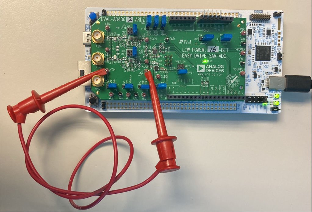
Figure 1 Biasing the EVAL-AD4062-ARDZ Inputs Without Signal Generator Hardware for Software Validation
If no signal generator is available, a jumper cable between the VREF and VCM test points can be used to bias the AD4060/ AD4062 analog inputs to VREF. This is preferred over connecting the amplifier inputs to GND, because the amplifier VEE rails are connected to GND by default.
Evaluation board hardware
The evaluation board includes the AD4060/AD4062 with companion circuitry for an out-of-the-box evaluation experience:
ADC: AD4060BCPZ/AD4062BCPZ (14-lead LFCSP)
Voltage reference: MAX6070 2.5V low-noise reference
Amplifiers: Two MAX44260 low-power, rail-to-rail op amps
Power regulator: ADP7118 3.3V LDO regulator
Digital Interface
The AD4060/AD4062 digital interface includes:
I3C bus: For reading and writing data (SDA and SCL on Arduino headers)
GP0/GP1: Two programmable GPIOs with multiple functions:
Data Ready (RDY) signal
Threshold interrupt (GP_INTR)
Device enable (DEV_EN) for AFE power cycling
Static high/low outputs
GPIO controller functionality (Linux only)
EEPROM: On-board I2C EEPROM for board identification
Power Domains
The evaluation board operates on the following power domains:
Power Rail |
Source |
Default Voltage |
|---|---|---|
+5V/VIN |
Arduino header (from carrier) |
5V |
VSUPPLY |
ADP7118 LDO regulator |
3.3V |
VDD |
VSUPPLY (via JP8) |
3.3V |
VIO |
IOREF from carrier (via JP1) |
3.3V |
VREF |
MAX6070 reference |
2.5V |
For more detailed hardware information, see the EVAL-AD4060/AD4062 User Guide.
Interfacing with IIO
The Linux IIO driver provides a complete feature set for the AD4060/AD4062, including threshold events, triggers, and GPIO controller support.
For language bindings and high level GUI tools see Libraries and GUI Tools.
Device enumeration
On the carrier Linux shell:
~$
iio_info
Or from a host PC via Ethernet:
~$
iio_info -u ip:192.168.2.1
The device appears as ad4062 or ad4060 depending on the part.
Available channels
The Linux driver exposes a single channel:
voltage0: Differential voltage input channel
Channel attributes
The channel provides the following standard IIO attributes:
Attribute |
Access |
Description |
|---|---|---|
|
Read |
Raw ADC value |
|
Read |
Scale factor to convert raw to mV (based on VREF) |
|
Read/Write |
Hardware gain calibration factor |
|
Read/Write |
Burst averaging ratio (1, 2, 4, 8, 16, …) |
|
Read |
List of supported oversampling ratios |
|
Read/Write |
Effective sampling frequency in Hz |
|
Read |
List of available sampling frequencies |
Reading voltage
Read the raw ADC value:
~$
iio_attr -c ad4062 voltage0 raw
Read the scale factor:
~$
iio_attr -c ad4062 voltage0 scale
Calculate the voltage in mV: voltage_mV = raw * scale
Configuring oversampling
View available oversampling ratios:
~$
iio_attr -c ad4062 voltage0 oversampling_ratio_available
Set oversampling ratio (value 1 disables oversampling):
~$
iio_attr -c ad4062 voltage0 oversampling_ratio 8
Note
When oversampling is enabled (ratio > 1), the device enters burst averaging mode, which increases the resolution but reduces the effective sample rate.
Configuring sampling frequency
View available sampling frequencies for the current oversampling ratio:
~$
iio_attr -c ad4062 voltage0 sampling_frequency_available
Set the sampling frequency:
~$
iio_attr -c ad4062 voltage0 sampling_frequency 1000000
Note
The available sampling frequencies depend on the current oversampling ratio. Changing the oversampling ratio will update the list of available frequencies.
Hardware gain calibration
The device supports hardware gain calibration to compensate for system gain errors:
# Read current calibration scale
~$
iio_attr -c ad4062 voltage0 calibscale
# Set calibration scale (normalized value)
~$
iio_attr -c ad4062 voltage0 calibscale 1.005
IIO buffered data capture
The Linux driver supports buffered data acquisition using IIO triggers.
Attach the trigger
The driver automatically registers a trigger named ad4062-dev0 (or similar).
Before enabling the buffer, attach the trigger:
# Find the trigger name
~$
ls /sys/bus/iio/devices/trigger*/name
# Set the current trigger
~$
echo ad4062-dev0 > /sys/bus/iio/devices/iio:device0/trigger/current_trigger
Enable the buffer
# Enable the channel for buffered capture
~$
echo 1 > /sys/bus/iio/devices/iio:device0/scan_elements/in_voltage0_en
# Set the buffer size
~$
echo 256 > /sys/bus/iio/devices/iio:device0/buffer/length
# Enable the buffer
~$
echo 1 > /sys/bus/iio/devices/iio:device0/buffer/enable
Read buffered data
Using iio_readdev:
~$
iio_readdev -s 1024 -b 256 ad4062 voltage0 > data.bin
Important
The trigger must be attached before enabling the buffer, otherwise the buffer will not capture data.
Threshold event monitoring
The AD4060/AD4062 support autonomous threshold monitoring. When enabled, the device continuously samples and compares the result against programmable thresholds, generating an event when the threshold is crossed.
Note
During threshold monitoring (monitor mode), the device operates autonomously. Any register access temporarily exits monitor mode. The Linux driver manages this automatically.
Event attributes
Threshold events are configured through event attributes under the channel:
# List event attributes
~$
ls /sys/bus/iio/devices/iio:device0/events/
Available event attributes:
Attribute |
Access |
Description |
|---|---|---|
|
Read/Write |
Enable threshold monitoring (0=disabled, 1=enabled) |
|
Read/Write |
Upper threshold value (raw ADC counts) |
|
Read/Write |
Hysteresis for upper threshold |
|
Read/Write |
Lower threshold value (raw ADC counts) |
|
Read/Write |
Hysteresis for lower threshold |
|
Read/Write |
Sampling frequency during monitor mode |
|
Read |
List of available monitor mode frequencies |
Setting thresholds
# Set upper threshold (rising)
~$
iio_attr -c ad4062 voltage0 events/thresh_rising_value 30000
# Set upper threshold hysteresis
~$
iio_attr -c ad4062 voltage0 events/thresh_rising_hysteresis 500
# Set lower threshold (falling)
~$
iio_attr -c ad4062 voltage0 events/thresh_falling_value 10000
# Set lower threshold hysteresis
~$
iio_attr -c ad4062 voltage0 events/thresh_falling_hysteresis 500
Configuring monitor mode sampling frequency
# View available frequencies
~$
iio_attr -c ad4062 voltage0 events/sampling_frequency_available
# Set monitor mode frequency
~$
iio_attr -c ad4062 voltage0 events/sampling_frequency 100000
Enabling threshold monitoring
# Enable threshold monitoring
~$
iio_attr -c ad4062 voltage0 events/thresh_either_en 1
# Disable threshold monitoring
~$
iio_attr -c ad4062 voltage0 events/thresh_either_en 0
Reading events
Events can be read from the character device:
# Monitor events (blocking read)
~$
cat /dev/iio:device0
Or use iio_event_monitor if available:
~$
iio_event_monitor ad4062
Important
While threshold monitoring is enabled, normal ADC reads are not available. Disable monitoring to return to regular sampling mode.
GPIO controller
When configured in the device tree, the GP0 and GP1 pins can be exposed as GPIO outputs. The GPIO controller feature allows you to control these pins as general-purpose outputs.
Device tree configuration
To enable GPIO controller support, add the gpio-controller property to the
device node in the device tree:
&i3c0 {
    adc@0,2ee007c0000 {
        compatible = "adi,ad4062";
        reg = <0x0 0x2ee 0x7c0000>;
        vdd-supply = <&vdd>;
        vio-supply = <&vio>;
        ref-supply = <&ref>;

        gpio-controller;
        #gpio-cells = <2>;
    };
};
GPIO indexing
The GPIO indices match the physical pin numbers:
GPIO 0 = GP0
GPIO 1 = GP1
If a GP pin is configured as an interrupt in the interrupt-names property,
it is not available as a GPIO.
Using GPIOs from userspace
# Export GPIO 1 (GP1)
~$
echo 1 > /sys/class/gpio/export
# Set direction to output
~$
echo out > /sys/class/gpio/gpio1/direction
# Set value high
~$
echo 1 > /sys/class/gpio/gpio1/value
# Set value low
~$
echo 0 > /sys/class/gpio/gpio1/value
# Unexport when done
~$
echo 1 > /sys/class/gpio/unexport
Low-power mode
The Linux driver automatically manages low-power mode. When the device is idle (not actively sampling), it enters low-power mode to reduce power consumption.
Threshold event monitoring disables low-power mode, as the device must continuously sample to detect threshold crossings.