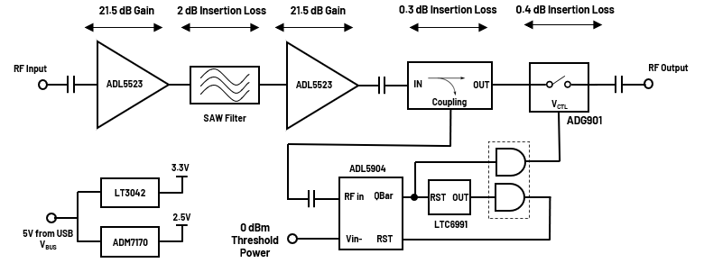
The CN0555 is a two-stage, USB-powered, RF low noise amplifier
that is optimized for receiver signal chains in the 433.92 MHz
industrial, scientific and medical (ISM) band. It provides a gain
of 40 dB through its RF band of operation using two ADL5523
amplifiers cascaded together, boosting signals for various
communication protocols such as
ISM,
MC-GSM,
W-CDMA,
TD-SCDMA, and
LTE .
It includes a high-speed overpower cutoff that protects sensitive
downstream equipment connected to the receiver system and automatically
turns back on when the RF power level drops within the acceptable range.
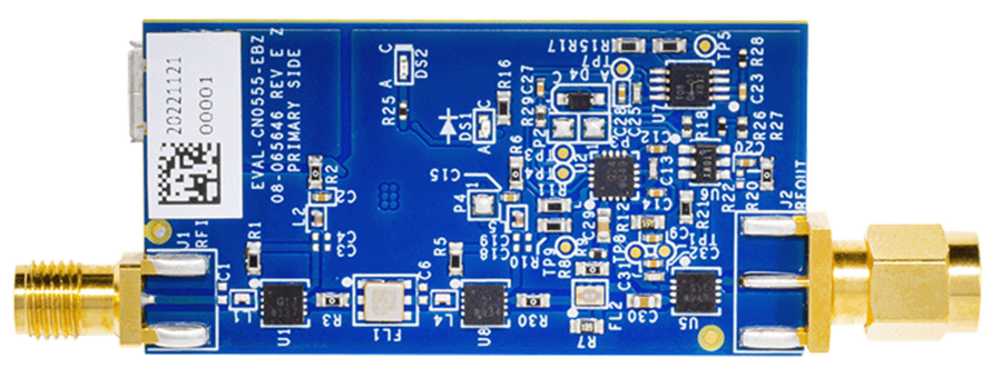
Designed to be used with the ADALM-PLUTO, the
EVAL-CN0555-EBZ features a small form-factor with dimensions
of 25.4 mm × 50.673 mm x 1.5748 mm (PCB only). The reference design
uses standard 50 Ω SMA coaxial connectors for its RF signal path —
for easy integration with any RF systems; a female connector is used
for the RF input and a male connector is used for the RF output.
Coplanar waveguides are used for the RF traces on the board, which
have a characteristic impedance of 50 Ω. A micro USB connector is used
for the input power, allowing the evaluation board to use most +5 V
wall-wart power supplies available in the market.
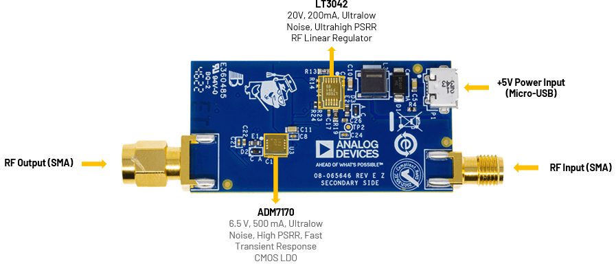
Figure 1 EVAL-CN0555-EBZ Reference Design Board
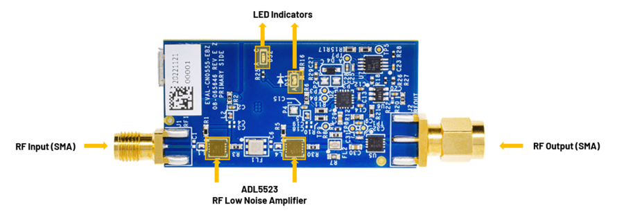
The CN0555 reference design features the ADL5523,
which is a high performance
GaAs pHEMT
low noise amplifier. It provides a high gain and low noise figure for
single down-conversion intermediate frequency (IF) sampling receiver
architectures, as well as direct down-conversion receivers. It is easy
to tune and only requires a few external components. The device can
support operation voltages from 3 V to 5 V and the current draw can be
adjusted with external bias resistors for applications requiring very
low power consumption.
The ADL5904 is a dual-function RF TruPwr detector that
operates from dc to 6 GHz. It provides rms power measurement along
with a programmable envelope threshold detection function. The
RMS power measurement function has a 45 dB detection range,
nominally from −30 dBm to +15 dBm. The rms power measurement
function also features low power consumption and an intrinsically
ripple-free error transfer function.
Figure 2 EVAL-CN0555-EBZ Simplified Block Diagram
Reference Design Hardware
Primary Side
Figure 3 CN0555 Primary Side
SMA Connectors
The SMA connectors are used for the RF input and output connections.
J1 is the RF Input SMA female connector that would be
connected to an antenna.
J2 is the RF Output SMA male connector that would be connected
to a radio or piece of RF equipment.
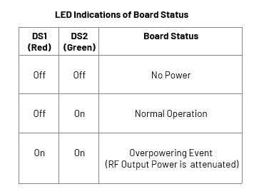
LED Indicators
The reference design uses two LEDs to indicate its current status.
The Red LED (DS1) lights up when an overpowering event occurs.
The Green LED (DS2) lights up when the power is present on the
board.
Figure 4 CN0555 LED Indications of Board Status
Secondary Side
Figure 5 CN0555 Secondary Side
Power Supply Connector
P1 is the micro USB port used to provide 5 V power to the board.
Connect Pluto to host PC or laptop using a micro USB cable in the
terminal with a USB symbol.
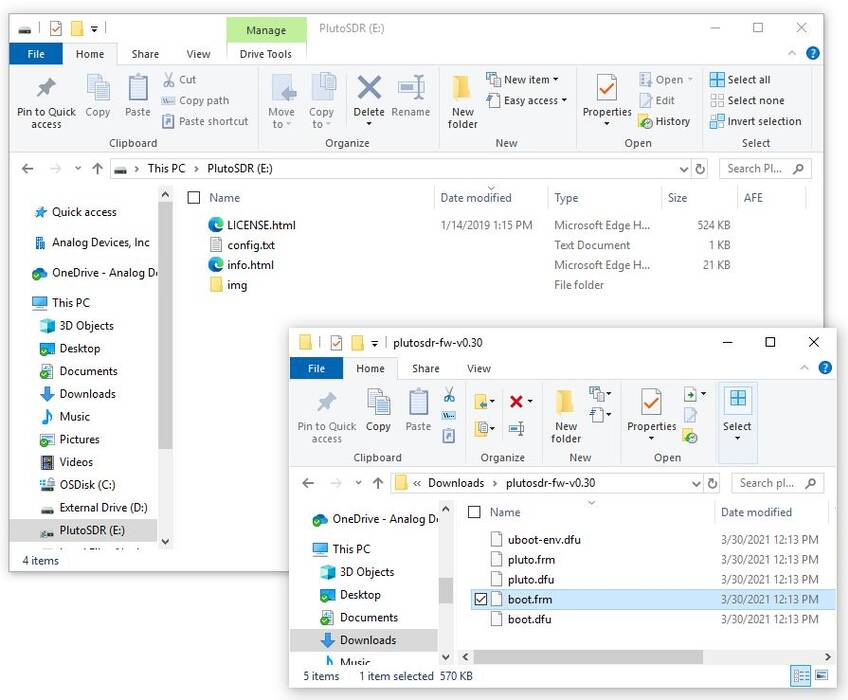
Open the Pluto mass storage device.
Open the unzipped firmware file.
Copy the file, pluto.frm, to the Pluto mass storage device.
Figure 6 Copying Pluto Firmware to the Pluto Mass Storage Device
This will cause LED1 to blink rapidly. This means that programming
is taking place. Do not remove power (or USB) while the device is
blinking rapidly. It takes approximately four minutes to properly
program the device.
Once the device finishes programming, it will reappear as a mass
storage device.
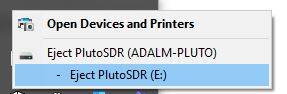
Eject (don’t unplug) the Pluto mass storage device.
Figure 7 Ejection of Pluto Mass Storage Device
Now, the USB cable can be safely disconnected from the PC.
Updating to the AD9364
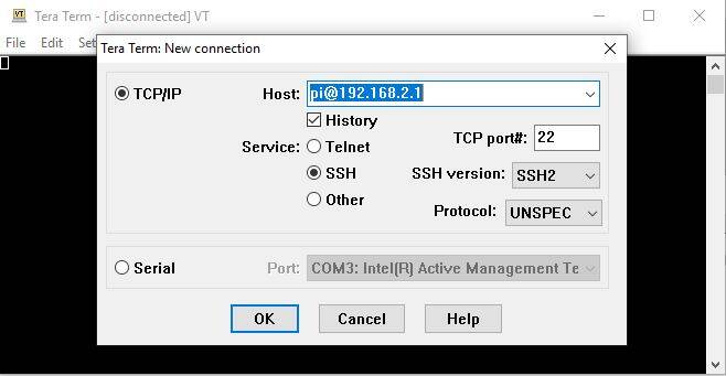
Connect again the Pluto to host PC using a micro USB cable.
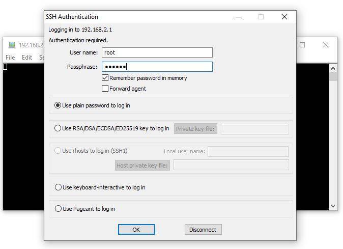
Open any serial terminal application (e.g., TeraTerm, Putty) and set
the SSH to 192.168.2.1, the username is root and password is
analog.
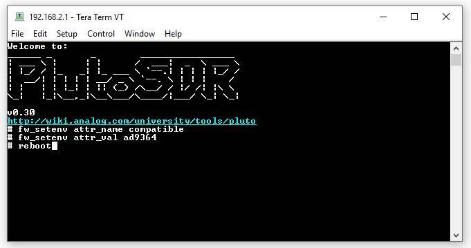
Figure 8 Copying Pluto Firmware to the Pluto Mass Storage Device
To change parameters to the AD9364 configuration, enter the
following commands line by line:
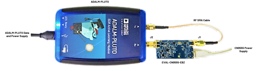
Connect P1 (micro USB) connector of the EVAL-CN0555-EBZ into
a PC USB port or 5 V USB charger.
Connect the micro USB to USB cable to a PC/laptop and the other end
to the ADALM-PLUTO data port.
The DS2 LED of CN0555 will automatically turn on, indicating
the board is powered on and is in operation.
Important
The ADALM-PLUTO can be configured using an IIO Oscilloscope, visit
IIO Oscilloscope to learn more about the tool.
IIO Oscilloscope
Important
Make sure to download/update to the latest version of IIO Oscilloscope
found on this link
Once done with the installation or an update of the latest IIO
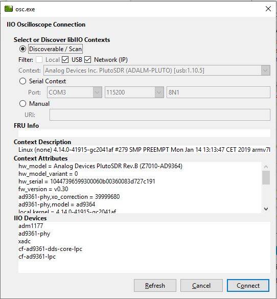
Oscilloscope, open the application. The user needs to supply a URI,
which will be used in the context creation of the IIO Oscilloscope and
the instructions can be seen in the previous section.
Press refresh to display available IIO devices, once the
ADALM-PLUTO appeared, press connect.
Figure 11 IIO Oscilloscope Configuration
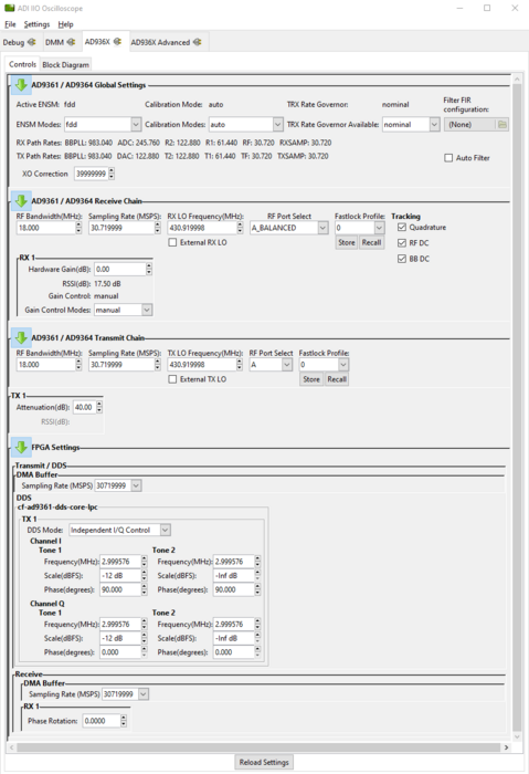
On the AD936x tab, set the required parameters for the
CN0555 to operate properly.
Figure 12 ADALM-PLUTO Settings
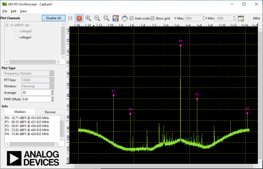
Using the capture window, you can see the RF output of the
CN0555 in the frequency domain.
Receive software update notifications and documentation updates, view
the latest videos, and more when you register your hardware.
Register
to receive all these great benefits and more!