USB-Powered, 5.8 GHz RF Power Amplifier with Overtemperature Management.
Overview
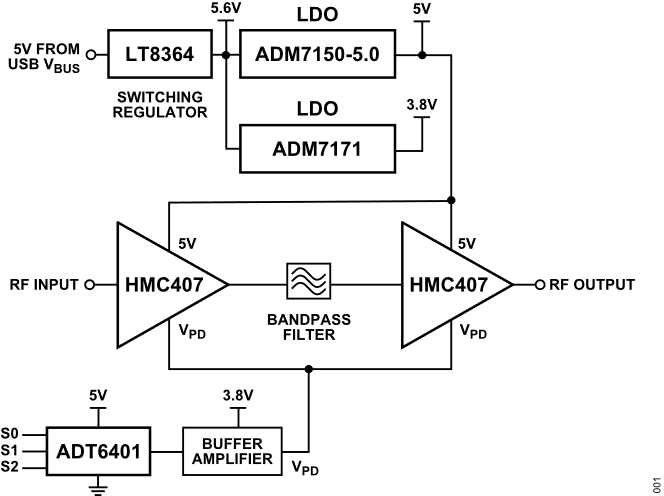
The EVAL-CN0523-EBZ is a USB-powered, RF power amplifier
that is optimized for transmitting signal chains in the 5.8GHz ISM band.
Using two HMC407 amplifiers cascaded together, the design
provides a gain of 28dB and return losses of more than 10dB throughout its RF
band of operation.
An overtemperature management feature is implemented on the
EVAL-CN0523-EBZ wherein the amplifiers are
automatically disabled when the board temperature reaches a preset threshold,
and it automatically returns to normal operation once the temperature falls
below the hysteresis point.
Designed to be used with the ADALM-PLUTO, or other
software defined radio platform, the board features a small form factor, with
dimensions of 25.4mm×50.8mmx1.5748mm (PCB only). The RF input and
output are designed with a 50Ω impedance, enabling direct connection between
the circuit and standard 50Ω systems.
A micro-USB connector is used for the input power, allowing the evaluation board
to use most 5V wall wart power supplies available in the market.
Figure 1 EVAL-CN0523-EBZ Block Diagram
Reference Design Hardware
Primary Side
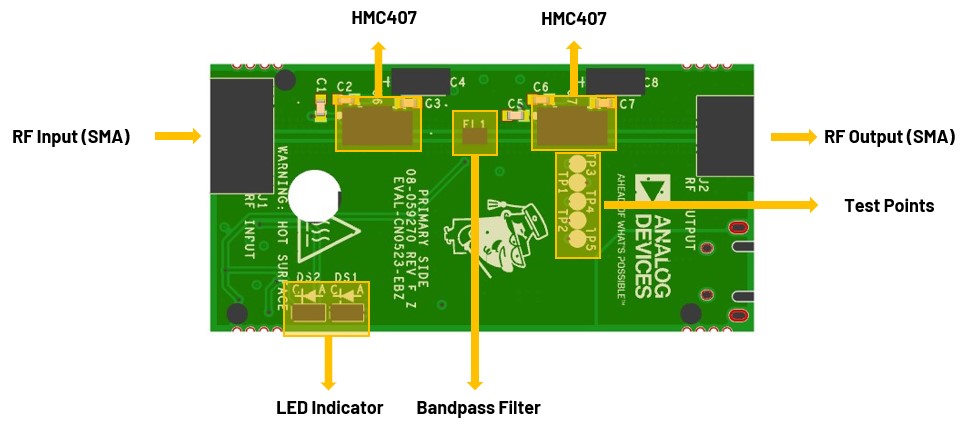
Figure 2 CN0523 Primary Side
SMA Connectors
The SMA connectors are used for the RF input and output connections:
J1 is the RF Input SMA male connector that would be connected to a
radio or piece of RF equipment. The maximum RF input level of the
EVAL-CN0523-EBZ is +10dBm. Do not use a higher input
level to avoid damaging the circuit.
J2 is the RF Output SMA FEmale connector that would be connected to
an antenna. The saturated output power (Psat) of EVAL-CN0523-EBZ
is +27dBm. Ensure that the RF load can handle the amplified RF signal.
Use an RF attenuator if necessary to avoid damage.
LED Indicators
The reference design uses two LEDs to indicate its current status:
LED Indications of Board Status
DS1
DS2
Board Status
Off
Off
No power
Off
On
Normal operation
On
On
Overtemperature
Secondary Side
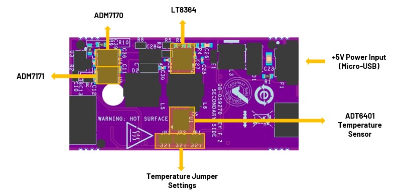
Figure 3 CN0523 Secondary Side
Power Supply Connector
P1 is the micro-USB port used to provide 5V power to the board. The total
typical supply current of the on-board RF amplifiers is 230mA.
Changing the Temperature Switch Trip Point (JP1, JP2, JP3)
The trip point of the temperature switch can be set using the solder jumpers
JP1, JP2, and JP3 as shown in the table below. When the board temperature
reaches the trip point, the ADT6401 will disable the two RF
amplifiers.
Figure 4 ADT6401 Jumper Settings
Selecting a Trip
Point for the
ADT6401
JP1 Setting
JP2 Setting
JP3 Setting
Trip Point
2 & 3
2 & 3
2 & 3
+45°C
1 & 2
2 & 3
2 & 3
+55°C
No solder jumper
2 & 3
2 & 3
+65°C
2 & 3
1 & 2
2 & 3
+75°C
1 & 2
1 & 2
2 & 3
+85°C
No solder jumper
1 & 2
2 & 3
+95°C
2 & 3
2 & 3
1 & 2
+65°C
1 & 2
2 & 3
1 & 2
+75°C
No solder jumper
2 & 3
1 & 2
+85°C
2 & 3
1 & 2
1 & 2
+95°C
2 & 3
No solder jumper
2 & 3
+105°C
1 & 2
No solder jumper
2 & 3
+115°C
No solder jumper
No solder jumper
2 & 3
+55°C
Important
Due to the considerable thermal dissipation of the RF amplifiers,
the last three options should not be used.
Two (2) micro-USB power adaptors or micro-USB to USB cables for powering
ADALM-PLUTO and EVAL-CN0523-EBZ
One (1) SMA male-to-male cable
One (1) SMA 30 dB RF attenuator
Firmware
For step-by-step procedure on how to update the Pluto Firmware, you can
use this user guide link.
The latest firmware version for the ADALM-PLUTO can be found here:
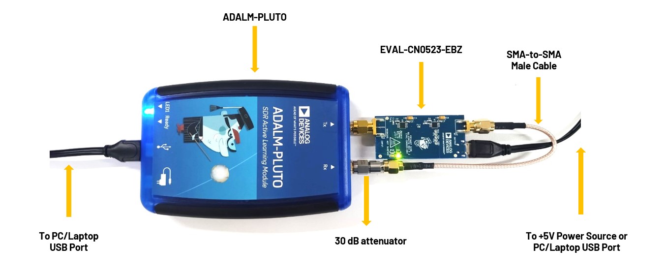
Connect directly the RX port of the ADALM-PLUTO to
a 30dB attenuator.
Connect RF Output (J2) of the EVAL-CN0523-EBZ to a 30dB
attenuator using a male-to-male SMA cable.
Connect P1 (micro-USB) connector of the EVAL-CN0523-EBZ
into a PC USB port or a 5V USB charger.
Connect the micro-USB to USB cable to a PC/laptop and the other end to the
ADALM-PLUTO data port.
The DS2 LED of EVAL-CN0523-EBZ will automatically
turn on, indicating that the board is powered on and is in operation.
Refer to the image below for the full hardware setup.
Figure 5 EVAL-CN0523-EBZ Test Setup
Warning
Connecting the CN0523 directly to the PlutoSDR input (Rx)
may result in an exceedance of its absolute maximum ratings
of +2.5dBm. Such an action may lead to permanent damage to the PlutoSDR. It is
strongly recommended to use a 30dB or 40dB attenuator at the RX input of
the ADALM PLUTO to avoid incurring damage.