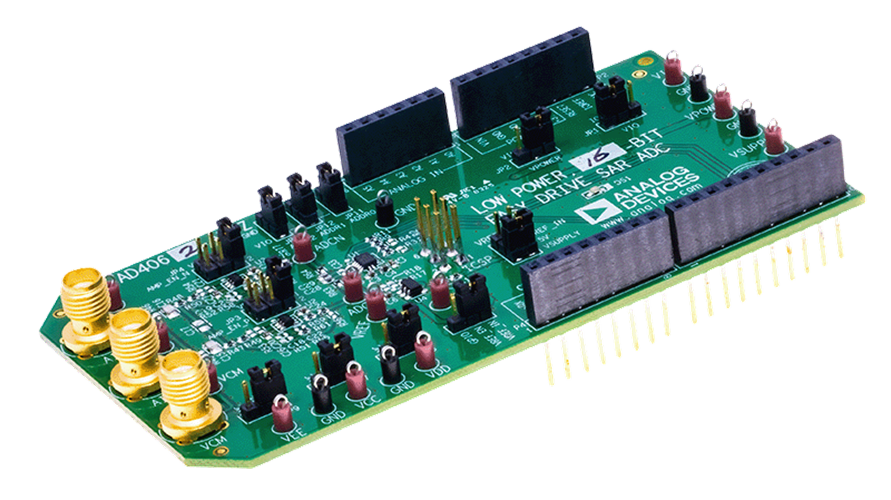
EVAL-AD4060/AD4062-ARDZ
Compact, Low Power, 12-Bit/16-Bit, 2 MSPS Easy Drive SAR ADCs.
The EVAL-AD4060-ARDZ and EVAL-AD4062-ARDZ evaluation boards enable quick and easy evaluation of the performance and features of the AD4060 or the AD4062, respectively.
The AD4060 and AD4062 are compact, low power, 12-bit or 16-bit (respectively) Easy Drive successive approximation register (SAR) analog-to-digital converters (ADCs) featuring an I3C digital interface. These devices offer exceptional performance with sample rates up to 2 MSPS while maintaining low power consumption, making them ideal for battery-powered precision measurement and monitoring applications.
The evaluation boards are designed to conform to the Arduino Uno Shield mechanical and electrical standard, enabling easy integration with various controller boards and development platforms.
Overview
This section provides a general overview of the evaluation board, all supported carriers, firmware options, and software tools.
The evaluation boards support multiple carrier platforms for both bare-metal (no-OS) and Linux environments:
Carrier |
no-OS |
Linux |
NUCLEO-H503RB |
✓ |
|
NUCLEO-H563ZI |
✓ |
|
Cora Z7S |
✓ |
|
DE10-Nano |
✓ |
Features
Evaluation Board Hardware:
Full-featured evaluation board for the AD4060 (12-bit) and AD4062 (16-bit)
USB power solution via carrier board
Single differential analog input with common-mode voltage control
SMA connectors for precision signal input
On-board MAX6070 2.5V voltage reference
MAX44260 low-power op amps for signal buffering
ADP7118 3.3V LDO regulator
Arduino Uno Shield compatible form factor
Digital Interface (I3C):
I3C digital interface for low-pin-count, high-speed communication
Support for multiple devices on a single I3C bus (up to 8 AD4060/AD4062s)
Two programmable GPIOs (GP0, GP1) with multiple functions:
Data Ready (RDY) signal
Threshold interrupt output
Device enable (DEV_EN) for AFE power cycling
General-purpose outputs (Linux only)
Software Features:
no-OS (bare-metal):
TinyIIO support for Libiio connectivity
Two channel modes: standard ADC and burst averaging
Configurable sample rates and averaging
Serial UART communication with host PC
Linux IIO:
IIO subsystem integration
Hardware-triggered buffered data acquisition
Autonomous threshold event monitoring
GPIO controller support
Automatic low-power mode management
Burst averaging with up to 2048x oversampling (AD4062)
GUI Applications:
IIO Oscilloscope for waveform visualization and FFT analysis
Scopy for advanced signal analysis
Real-time data capture and export
Language Bindings:
Evaluation board kit contents
EVAL-AD4060-ARDZ or EVAL-AD4062-ARDZ evaluation board
Equipment needed
Host PC (Windows, Linux, or macOS)
One of the supported carrier boards:
STM32 Nucleo board for no-OS evaluation
Cora Z7S or DE10-Nano for Linux evaluation
Precision signal source with SMA cable
USB cable for carrier connection
Hardware
The evaluation board connects to the Arduino Uno compatible headers of the carrier board, providing both power and digital communication.
Power Configuration:
When powering from the carrier USB:
Set JP2 jumper on the evaluation board to the +5V position
Connect carrier to PC via USB
The DS1 LED on the evaluation board should illuminate
When using an external power supply:
Set JP2 jumper on the evaluation board to the VIN position
Provide 7-12V DC to the carrier’s external power input
Connect carrier to PC via USB for communication
The DS1 LED on the evaluation board should illuminate
I3C Address Configuration:
The evaluation board includes jumpers JP10, JP11, and JP12 to configure the I3C device address via ADDR[2:0] pins. Default firmware requires all address pins set to GND (ADDR[2:0] = 000).
For detailed hardware specifications, schematics, and board layout, see the EVAL-AD4060-ARDZ and EVAL-AD4062-ARDZ product pages, including the user guide and design support files.
Overview
This section summarizes all source code and related documentation for the evaluation board.
Working with the source code requires prior knowledge of software development and HDL design (for FPGA-based carriers). We provide pointers to introductory guides, though their scope is limited to topics particularly relevant to our codebase and do not replace the full documentation of the tools used.
Drivers
The driver source code is available at:
Firmware |
Device Support |
Source code |
Documentation |
no-OS |
AD4050/AD4052/AD4056/AD4058/AD4060/AD4062 (SPI & I3C) |
||
Linux |
AD4060/4062 (I3C only) |
Note
The Linux driver is currently under review for upstream inclusion in the mainline kernel. See the patch series on linux-iio mailing list for the latest status.
Driver Architecture:
no-OS: The driver is divided into a core driver (device control) and a TinyIIO layer (IIO interface for Libiio connectivity over serial). The core driver supports both SPI (AD405x) and I3C (AD406x) variants.
Linux: The driver is integrated into the IIO subsystem and always exposes the device via Linux Industrial I/O Subsystem. It provides full support for IIO triggers, events, buffers, and GPIO control.
HDL reference design
The FPGA-based carriers (Cora Z7S, DE10-Nano) use an HDL design to instantiate the I3C controller and interface with the evaluation board.
Project source:
Source code: projects/ad4062_ardz
Documentation: AD4062-ARDZ HDL project
Features:
I3C controller with offload support*
PWM generator for periodic sampling
Integration with the HDL Reference Designs framework
AXI DMA for high-throughput data capture
Get started with the HDL reference design by reading the User Guide.
* Offload is not supported by the Linux driver.
Design files
User Guides
This section is for everyone using the evaluation board. It provides step-by-step instructions on hardware setup, firmware building and flashing, and interacting with the device using various software tools.
The following user guides are available:
Help and Support
For questions and more information, please visit:
All the products described on this page include ESD (electrostatic discharge) sensitive devices. Electrostatic charges as high as 4000V readily accumulate on the human body or test equipment and can discharge without detection. Although the boards feature ESD protection circuitry, permanent damage may occur on devices subjected to high-energy electrostatic discharges. Therefore, proper ESD precautions are recommended to avoid performance degradation or loss of functionality. This includes removing static charge on external equipment, cables, or antennas before connecting to the device.