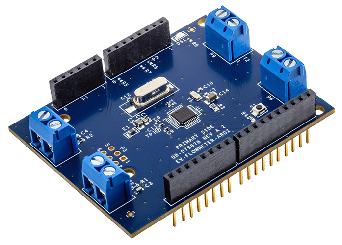
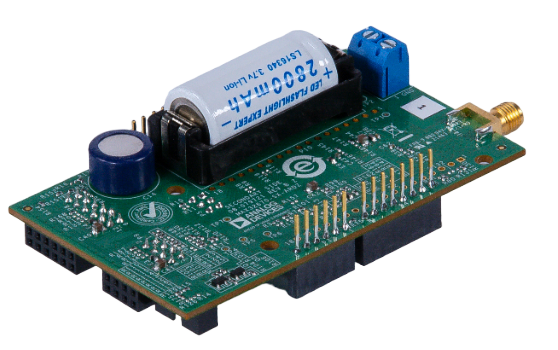
EV-FLOWMETER-ARDZ
Sensor for Flow Rate Metering
Overview
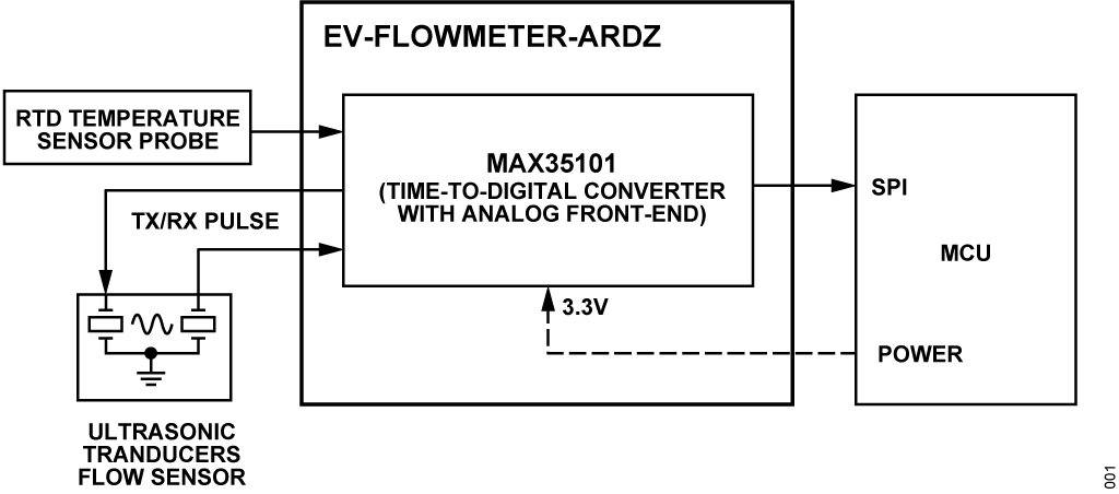
The EV-FLOWMETER-ARDZ sensor is an advanced and efficient solution for flow measurement, suitable for utility and industrial applications. The ultrasonic time-of-flight technology, coupled with the integrated functions of the MAX35101 time-to-digital converter, addresses the limitations of mechanical flow meters and offers improved accuracy and longevity.
Features
High accuracy flow measurement for billing and leak detection
Time-to-digital accuracy down to 20 ps
Measurement range up to 8 ms
Two (2) single-stop channels
High accuracy temperature measurement for precise heat and flow calculations
Up to four (4) 2-wire sensors
PT1000 and PT500 RTD support
Maximizes battery life with low device and overall system power
Low 10 μA ToF measurement and <125 nA duty-cycled temperature measurement
Event-timing mode reduces host microcontroller
Applications
Ultrasonic heat meters
Ultrasonic water meters
Ultrasonic gas meters
Utility metering
Environmental monitoring
Block Diagram
Hardware Design
Components and Connections
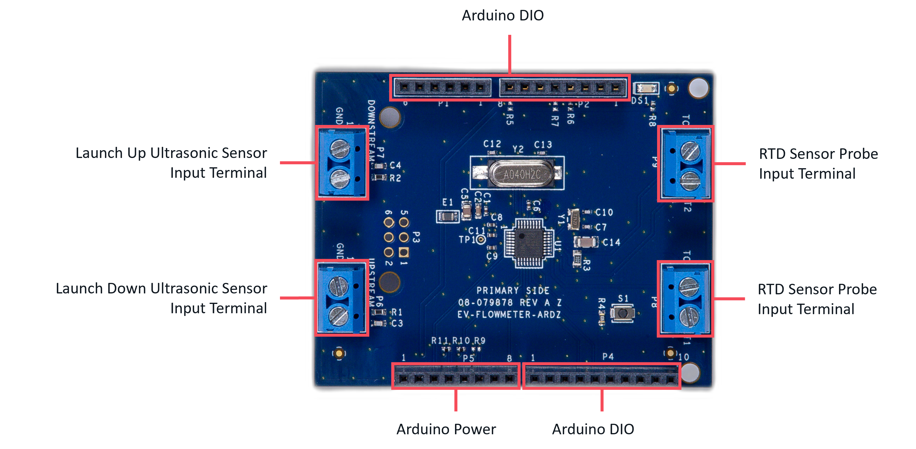
Peripheral Connectors
The following standard connectors are provided on the board for customer to use:
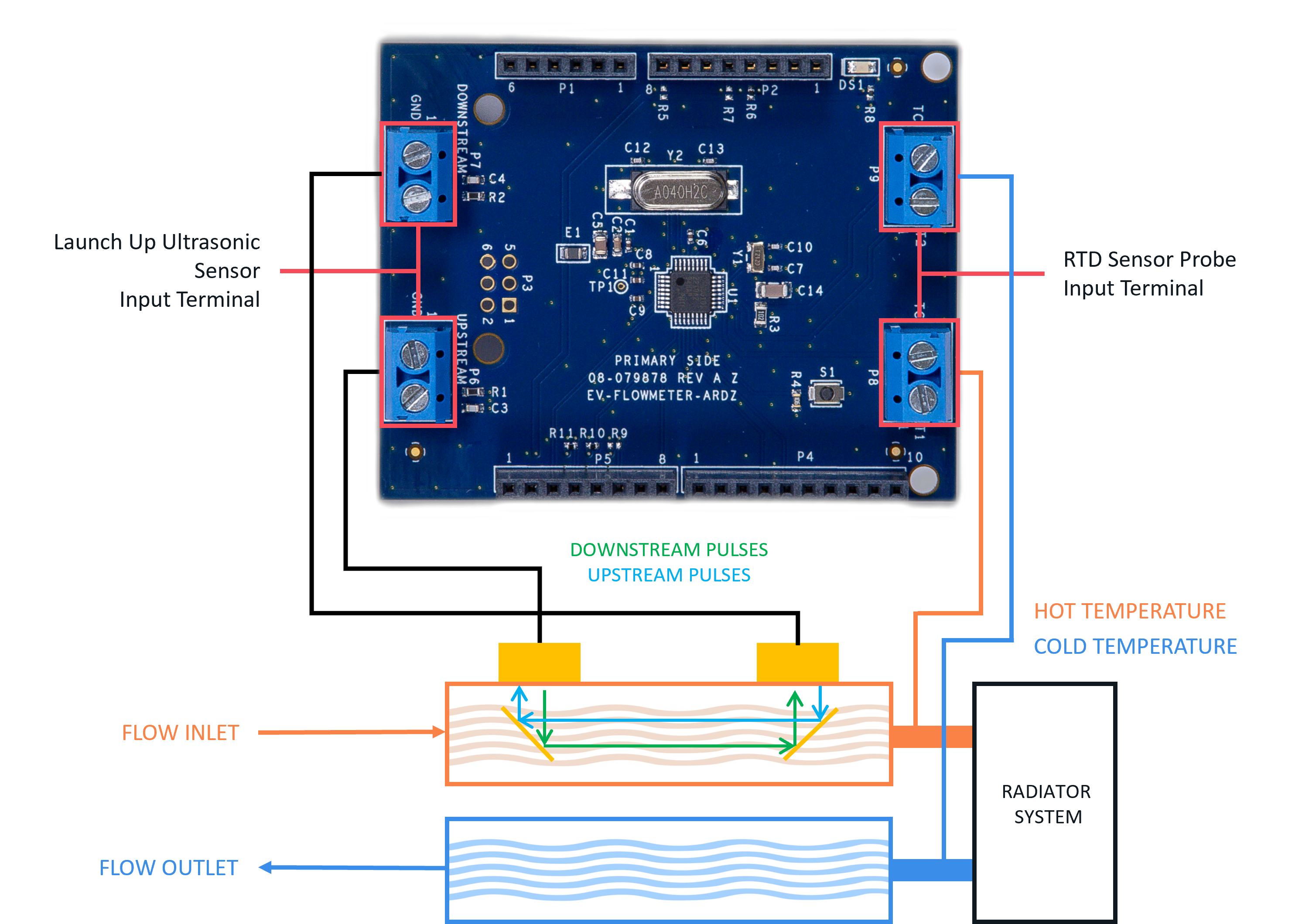
Launch up and down ultrasonic sensor terminal block headers
PT1000/500 platinum resistive temperature detectors (RTD) terminal block headers
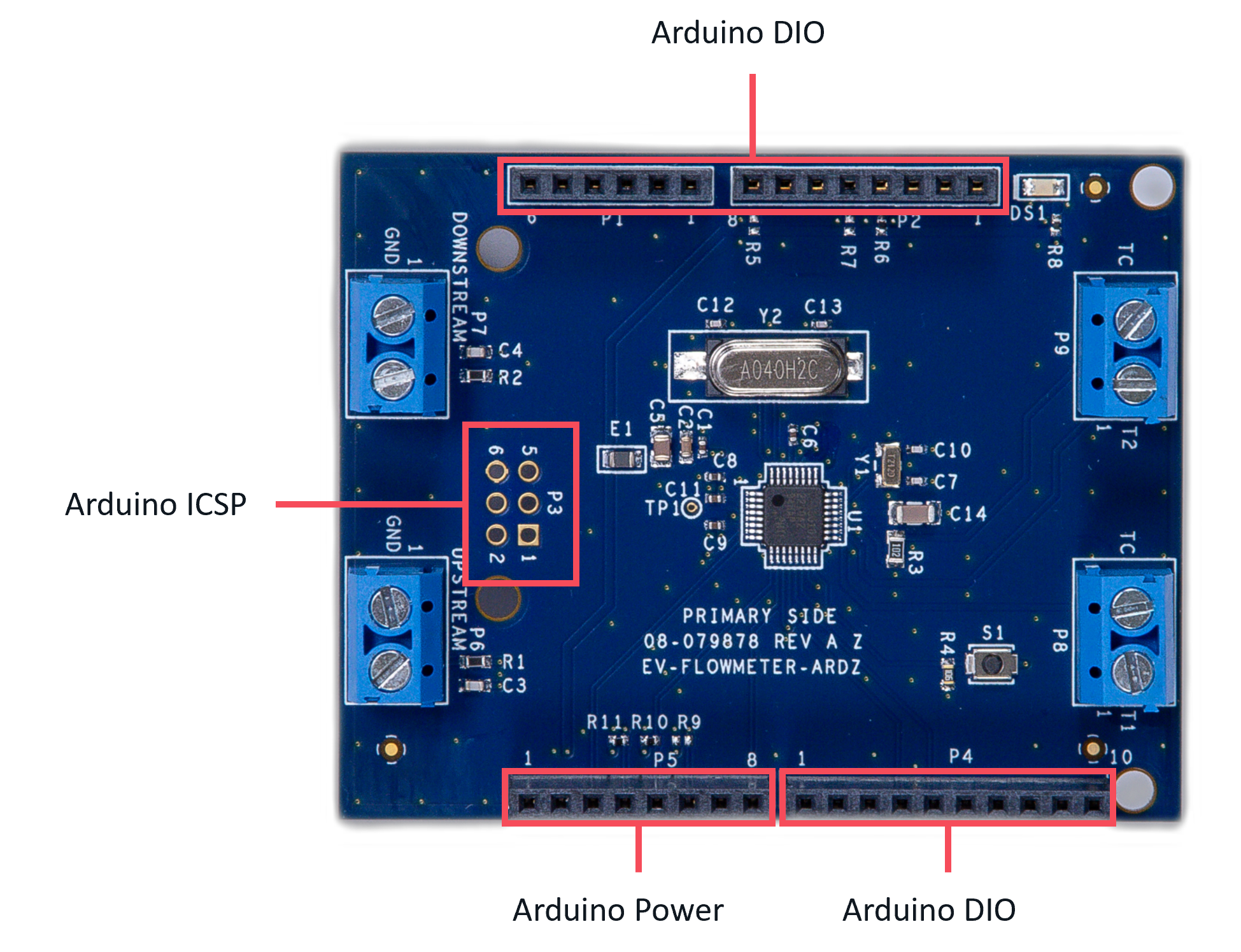
Arduino connector
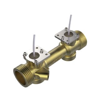
Sensor Probe
When using this Arduino board, a general-purpose ultrasonic flow rate sensor can be used. An example of a probe is the Flow Transducer with Pipe (Model:HS0003) from Audiowell Sensor Technology, as shown below:
Resonant Frequency |
975 ±30 kHz |
Resonant Impedance |
≤ 110 Ω |
Static capacitance |
1350 ±20% pF |
Pressure Resistance |
1.6 Mpa |
Permanent Flowrate |
2.5 m³/h |
Max Flowrate |
5.0 m³/h |
Min Flowrate |
0.050 m³/h |
Environmental Temperature |
+5°C ~ +55°C |
Diameter |
DN20 |
For temperature measurement, this board supports up to two 2-wire PT1000/500 platinum resistive temperature detectors (RTD) and the connections can be seen on the diagram as shown below: <note important>An RTD sensors or a dummy sensor (1k Resistor) for each terminal are required in order to run and capture the flow rate. </note>
Digital Interface (Arduino)
The Arduino interface is a standardized digital interface for various digital communication protocols such as SPI, I2C, and UART. These interface types were standardized by Arduino, which is a hardware and software company. Complete details on the PMOD specification can be found here.
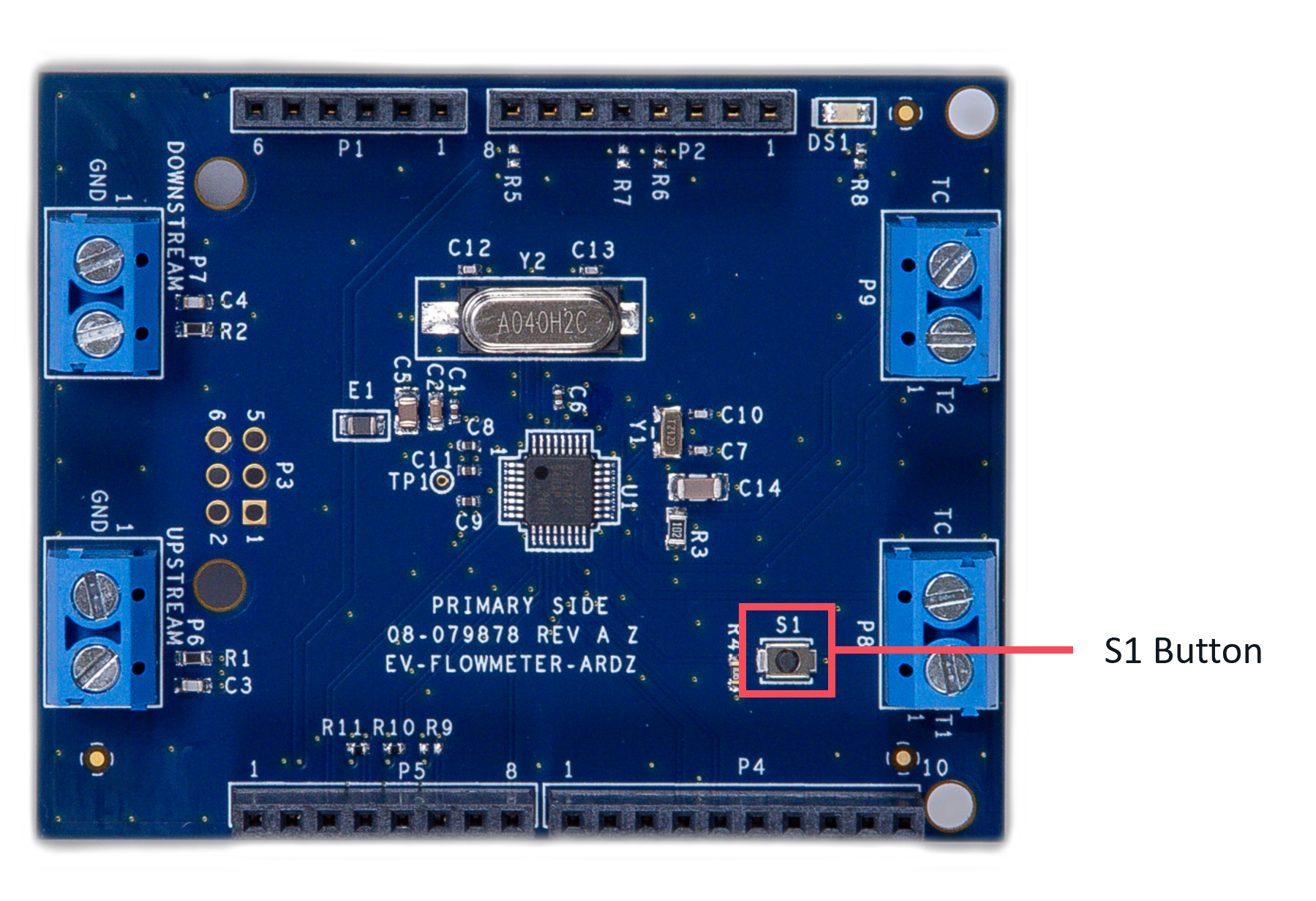
Push Button
The board provides a button, S1, to test tamper detection through its CMOS digital input.
Applications
The EV-FLOWMETER-ARDZ can be used with the MAX32670-SX-ARDZ Base Board, which is a long-range wireless radio development platform based on MAX32670 ultralow power Arm Cortex-M4 microcontroller and SX1261 RF transceiver.
Using these platforms together enables users to design solutions based on low-power, long range proprietary radio communication technique that is suitable for customized heat/flow meters.
To learn more about the Long Range Wireless Radio solution developed by Analog Devices, visit the AD-MAX32SXWISE-SL Long Range Wireless Radio Development Kit User Guide.
System Setup
PHASE 1: Hardware Setup
Note that this setup only applies for MAX32670-SX-ARDZ Base Board. Users may use a different base board or microcontroller, however the firmware built for this demo application cannot be used as this is specifically designed for the MAX32670-SX-ARDZ.
Equipment Needed
One (1) MAX32670-SX-ARDZ Base Board
One (1) EV-FLOWMETER-ARDZ Sensor Node
One (1) MAX32625PICO Rapid Development Platform with 10-pin ribbon cable with firmware image
One (1) CR123A Battery or any equivalent external DC power supply (+3V to +4.7V). Note that this is not included in the kit
One (1) Micro USB to USB cable
Host PC (Windows 10 or later)
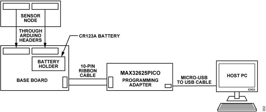
Insert one CR123A battery (3V to 4.7V) into the battery holder (BT1 connector) of the MAX32670-SX-ARDZ Base Board.
Make sure to check for the battery polarity in the BT1 connector, refer to the figure below. The DS3 LED will light up indicating that you have inserted the battery correctly and that power is provided in the base board.
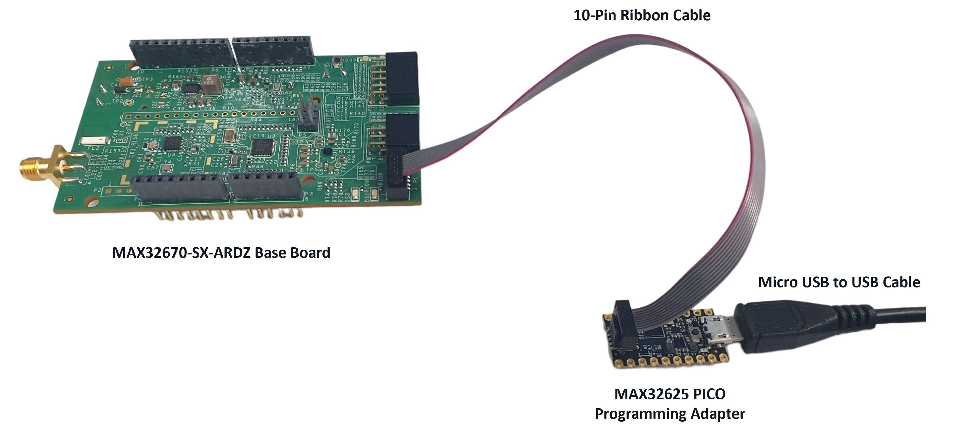
Connect the EV-FLOWMETER-ARDZ Sensor Node to the MAX32670-SX-ARDZ Base Board by aligning the corresponding Arduino headers on each board.
Connect the MAX32625PICO programming adapter to the MAX32670-SX-ARDZ Base Board through the 10-pin ribbon cable.
Tip
Make sure that the MAX32625PICO programming adapter has been flashed with the correct image before connecting it to the MAX32670-SX-ARDZ Base Board.
How to flash the firmware image in the MAX32625PICO
Download the firmware image: MAX32625PICO Firmware Image for MAX32670
Do not connect the MAX32625PICO to the MAX32670-SX-ARDZ Base Board yet.
Connect the MAX32625PICO to the Host PC using the micro USB to USB cable.
Press the button on the MAX32625PICO. (Do not release the button until the MAINTENANCE drive is mounted).
Release the button once the MAINTENANCE drive is mounted.
Drag and drop (to the MAINTENANCE drive) the firmware image.
After a few seconds, the MAINTENANCE drive will disappear and be replaced by a drive named DAPLINK. This indicates that the process is complete, and the MAX32625PICO can now be used to flash the firmware of the MAX32670-SX-ARDZ Base Board.
Connect the MAX32625PICO programming adapter to the Host PC using the micro USB to USB cable.
Once you have completed this setup, proceed to PHASE 2 found in ADI Long Range Wireless Radio Software User Guide.
Resources
Design and Integration Files
Download
EV-FLOWMETER-ARDZ Design Support Package Rev. A
Schematic
Bill of Materials
Layout
Fabrication Files
Help and Support
For questions and more information about this product, connect with us through the Analog Devices Engineer Zone.