The EVAL-CN0521-EBZ is a USB-powered, RF low noise amplifier (LNA)
that is optimized for receiving signal chains in the 2.4GHz ISM band.
Using two HMC639 amplifiers cascaded together, the design provides
a gain of 21dB and return losses of more than 10dB throughout its RF
band of operation.
The board includes a high speed overpower cutoff that protects sensitive
downstream equipment connected to the receiver system. The receiver system
also automatically turns back on when the RF power level drops within the
acceptable range.
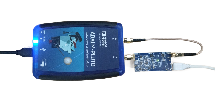
Designed to be used with the ADALM-PLUTO,
the EVAL-CN0521-EBZ features a small form factor,
with dimensions of 25.4mm×49.6mm×1.5748mm (PCB only).
The RF input and output are designed with a 50Ω impedance, enabling direct
connection between the circuit and standard 50Ω systems.
A micro-USB connector is used for the input power, allowing the evaluation
board to use most 5V wall wart power supplies available in the market.
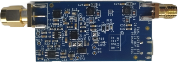
Figure 1 EVAL-CN0521-EBZ Reference Design Board
The EVAL-CN0521-EBZ features the HMC639, which is a GaAs,
pHEMT, high linearity, low noise amplifier operating between 0.2GHz to
4GHz for various applications such as fixed-wireless, cellular, and
CATV. This low noise RF amplifier does not require any external matching
circuitry to operate.
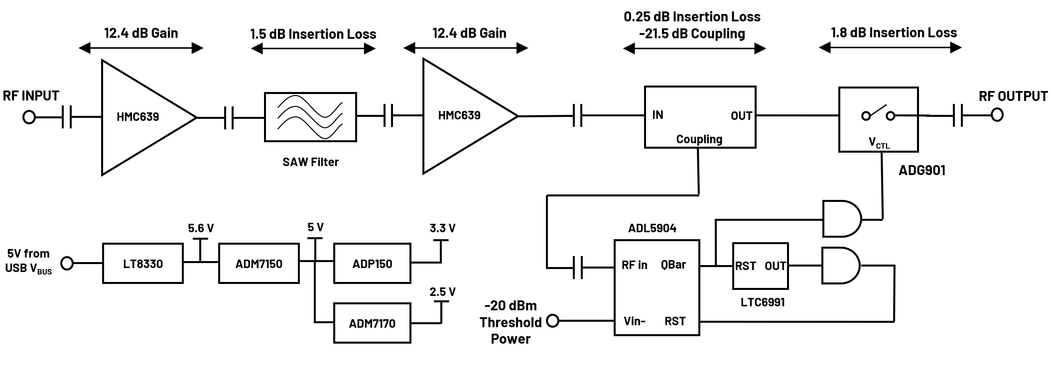
Figure 2 EVAL-CN0521-EBZ Simplified Block Diagram
Components
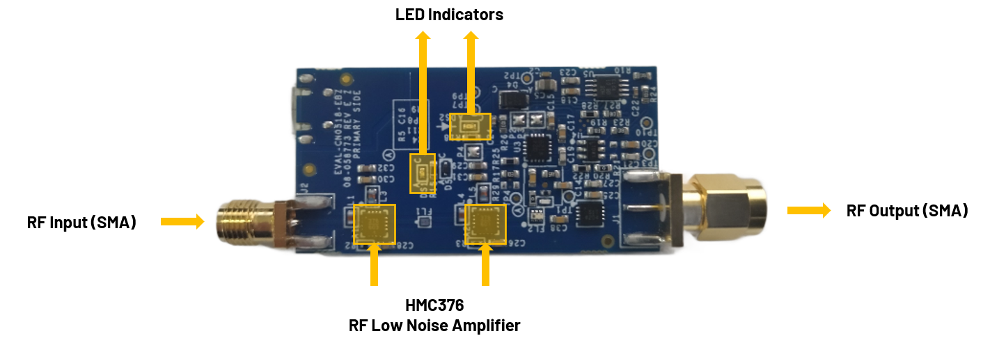
Figure 3 CN0521 Primary Side
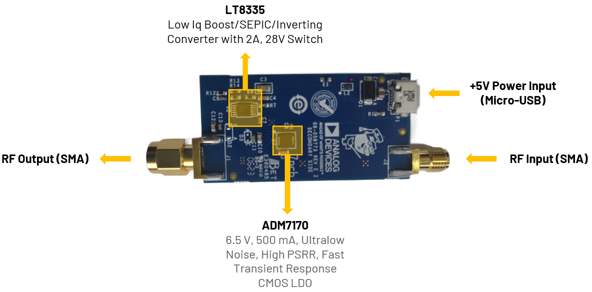
Figure 4 CN0521 Secondary Side
SMA Connectors
The SMA connectors are used for the RF input and output connections.
RF Port
Reference Designator
Description
RF Input (SMA male connector)
J1
Connect to a radio
or piece of RF
equipment
RF Output (SMA female connector)
J2
Connect to an
antenna
LED Indicators
The reference design uses two LEDs to indicate its current status:
RF Port
Reference Designator
Description
Green LED
(DS2)
Indicates that power is present on the board
Red LED
(DS1)
Indicates when an overtemperature event
occurs
This table shows the board status when the various LEDs are ON/OFF.
Green LED
Red LED
Board Status
OFF
OFF
No Power
ON
Off
Normal RF Operation
ON
ON
Overpower Event (RF Output Attenuated)
Power Supply Connector
P1 is the micro-USB port used to provide 5V power to the board.
Connect P1 (micro-USB) connector of the EVAL-CN0521-EBZ
into a PC USB port or 5 V USB charger.
Connect the micro-USB to USB cable to a PC/laptop and the other end
to the ADALM-PLUTO data port.
The DS2 LED of EVAL-CN0521-EBZ will automatically turn on,
indicating the board is powered on and is in operation.
IIO Oscilloscope
Important
Make sure to download/update to the latest version of IIO Oscilloscope
found on this
link.
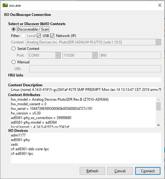
Once done with the installation or an update of the latest IIO
Oscilloscope, open the application. The user needs to supply a URI,
which will be used in the context creation of the IIO Oscilloscope.
The instructions can be seen in the previous section.
Press Refresh to display available IIO devices. Once the
ADALM-PLUTO appeared, press connect.