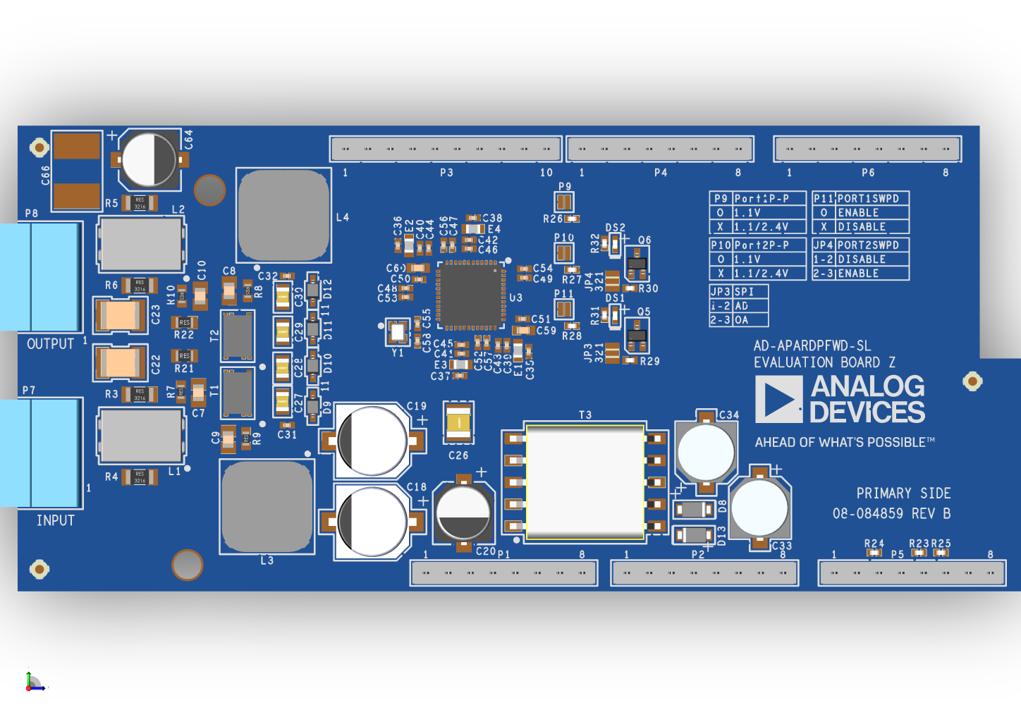
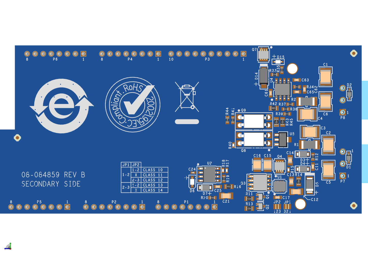
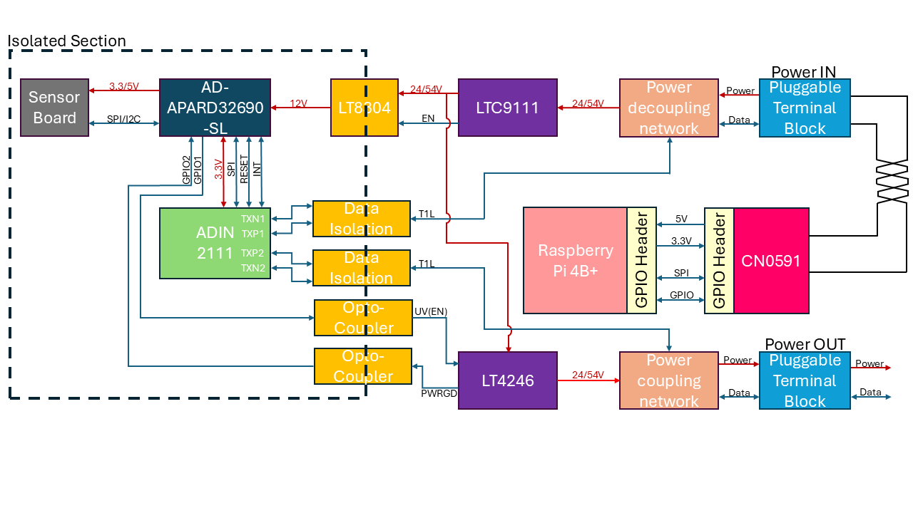
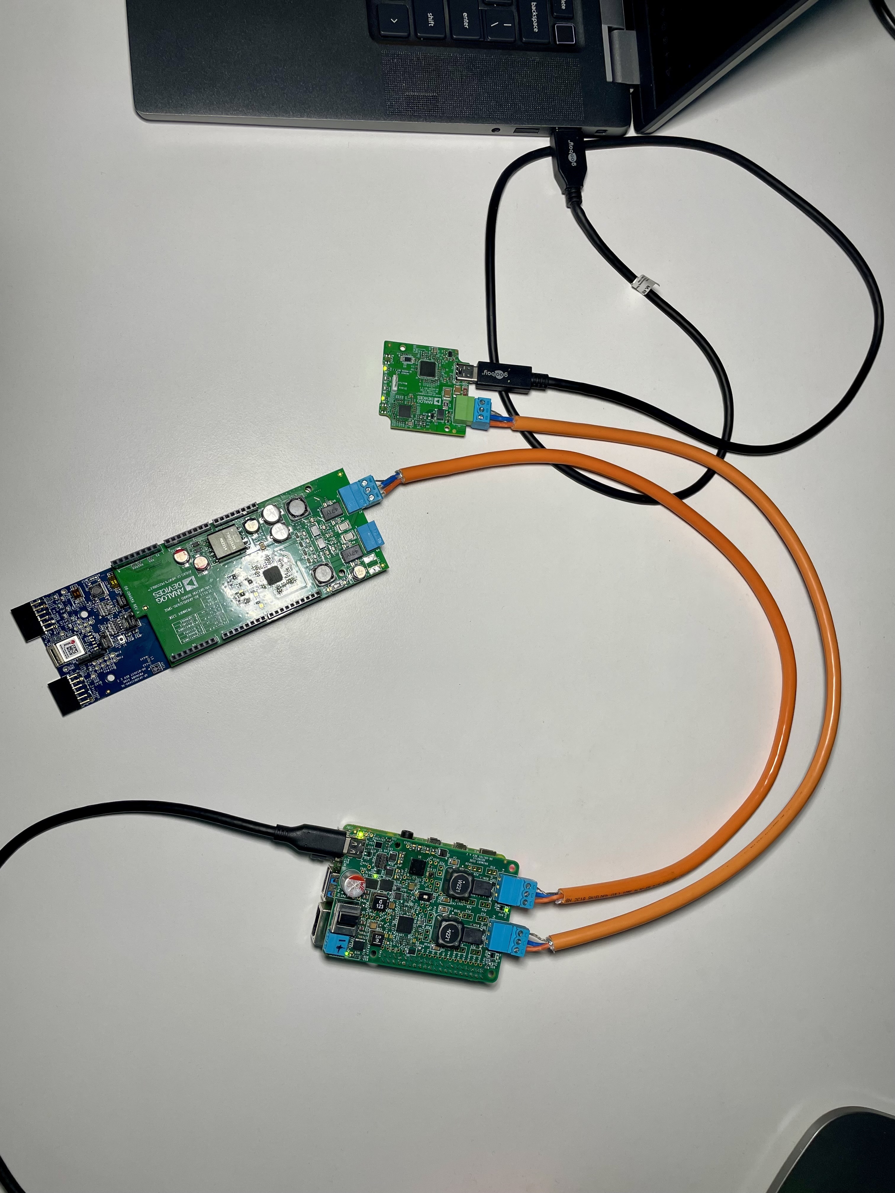
AD-APARDPFWD-SL

2-port 10BASE-T1L Arduino Shield with SPoE Power Forwarding

General Description

https://media.githubusercontent.com/media/analogdevicesinc/documentation/main/docs/solutions/reference-designs/ad-apard32690-sl/ad-apardpfwd-sl/apard-pfwd-top-iso.png

Figure 1 AD-APARDPFWD-SL

The AD-APARDPFWD-SL is a 10BASE-T1L power forwarder with Single Pair Power over Ethernet (SPoE) for development of field devices and applications on a AD-APARD32690-SL platform board. The SPoE powered device (PD) and isolated flyback regulator provide 12 V power to the platform board. SPoE Class 10-12 (24 V nominal) and Class 13-14 (55 V nominal) are supported.

Designed for use on the AD-APARD32690-SL platform, the AD-APARDPFWD-SL hardware features Arduino Mega Form-factor headers, and two 10BASE-T1L ports for connecting to a 10BASE-T1L Power Sourcing Equipment (PSE) such as the AD-RPI-T1LPSE-SL 2-port 10BASE-T1L w/SPoE PSE Development Platform.

To allow board stacking and development of field device applications using Arduino shields, the AD-APARDPFWD-SL has extra tall headers that allows other Arduino shields to be stacked on top of it.

The design also features a complete power and data isolation to the host AD-APARD32690-SL.

Evaluation Board Hardware

Primary Side

https://media.githubusercontent.com/media/analogdevicesinc/documentation/main/docs/solutions/reference-designs/ad-apard32690-sl/ad-apardpfwd-sl/apard-pfwd-top-with-labels.png

Figure 2 AD-APARDPFWD-SL Primary Side

The AD-APARDPFWD-SL uses 2 10BASE-T1L ports. One port is the input port (P7), which supplies power to the AD-APARD32690-SL platform board, and the other port is the output port (P8), which can be used to connect to another 10BASE-T1L device or to daisy chain multiple devices. The input port is connected to the LTC9111 SPoE PD controller, which extracts the SPoE power from the 10BASE-T1L cable and provides it to the LT8304 isolated flyback regulator. The LT8304 provides a regulated 12V.

Power is supplied to the AD-APARD32690-SL platform board via PIN8 of the P1 header.

The onboard ADIN2111 PHY provides the 10BASE-T1L connection to the host platform board. The ADIN2111 is connected to the AD-APARD32690-SL platform board via the P5 and uses the SPI4 port of the AD-APARD32690-SL.

The ADIN2111 supports selectable peak-to-peak transmit levels of 1.1V or 2.4V for each PHY. To select the desired level, configure the P9 and P10 solder jumpers for PHY1 and PHY2, respectively:

  • Disconnected: Sets the transmit level to 2.4V

  • Shorted: Sets the transmit level to 1.1V

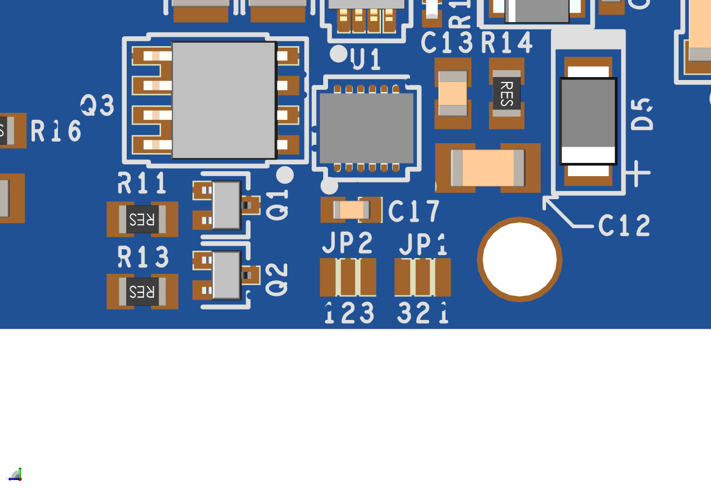
The generic SPI protocol is half duplex. Therefore, it is not possible to write frame data into the MAC_TX register and read from the MAC_RX register at the same time. To achieve full duplex transmission on Ethernet at 10 Mbps, OPEN Alliance SPI must be used. To select which SPI protocol to use, the JP3 solder jumper should be configured as follows:

JP3 Position

SPI Mode

Across 1 and 2

AD (Generic SPI)

Across 2 and 3

OA (OPEN Alliance SPI)

The ADIN2111 supports software power-down after power-up / reset for each port independently. To utilize this feature:

  • Short jumper P11 to enable the software power-down for PHY1.

  • In order to enable the software power-down for PHY2, configure JP4 solder jumper with the following settings

JP4 Position

Software Power-down

Across 1 and 2

Disabled

Across 2 and 3

Enabled

Secondary Side

https://media.githubusercontent.com/media/analogdevicesinc/documentation/main/docs/solutions/reference-designs/ad-apard32690-sl/ad-apardpfwd-sl/apard-pfwd-bottom-with-labels.png

Figure 3 AD-APARDPFWD-SL Secondary Side

SPoE PD Power Class Selection (JP1 and JP2)

By default, the LTC9111 SPoE PD controller included in the AD-APARDPFWD-SL circuit is configured for PD Class 12. If a different PD class is required for the application, the JP1 and JP2 solder jumpers should be reconfigured to match the desired class.

https://media.githubusercontent.com/media/analogdevicesinc/documentation/main/docs/solutions/reference-designs/ad-apard32690-sl/ad-apardpfwd-sl/apard-pfwd-classes.png

Figure 4 SPoE PD Power Class Jumpers

PD Class

JP1 Position

JP2 Position

VPD(min)

VPD(max)

I(max)

PPD(max)

10

Across 1 and 2

Across 1 and 2

14 V

30 V

92 mA

1.23 W

11

Across 1 and 2

Disconnected

14 V

30 V

240 mA

3.20 W

12

Across 1 and 2

Across 2 and 3

14 V

30 V

632 mA

8.40 W

13

Across 2 and 3

Across 1 and 2

35 V

58 V

231 mA

7.70 W

14

Across 1 and 3

Disconnected

35 V

58 V

600 mA

20.0 W

Warning

Do not use PD Classes 15!

The AD-APARDPFWD-SL evaluation board is not designed to handle the class 15’s power specifications.

System Setup

Required Equipment

Hardware

  • AD-APARDPFWD-SL Circuit Evaluation Board

  • AD-APARD32690-SL

  • 10BASE-T1L media converter, either:

  • Power Source, either:

    • AD-RPI-T1LPSE-SL 2-port 10BASE-T1L w/SPoE PSE Development Platform

      • Raspberry Pi Model 3B (or higher)

      • Micro-SD Card for Raspberry Pi

    • Other 10BASE-T1L Power Coupling Network Board w/ SPoE PSE

  • MAX32625PICO or any other similar programmer supporting the SWD interface

Block Diagram

Setup with SPoE via PSE

The AD-RPI-T1LPSE-SL 2-port 10BASE-T1L w/SPoE PSE Development Platform provides a complete solution for powering the AD-APARDPFWD-SL evaluation board and the AD-APARD32690-SL platform board via SPoE.

https://media.githubusercontent.com/media/analogdevicesinc/documentation/main/docs/solutions/reference-designs/ad-apard32690-sl/ad-apardpfwd-sl/apard-pfwd-block-diagram.png

Figure 5 Test Setup with SPoE via PSE

Basic Operation

https://media.githubusercontent.com/media/analogdevicesinc/documentation/main/docs/solutions/reference-designs/ad-apard32690-sl/ad-apardpfwd-sl/apard-pfwd-setup.png

Figure 6 Complete Evaluation Setup

To establish a 10BASE-T1L connection to an AD-APARD32690-SL using the AD-APARDPFWD-SL evaluation board and ping the AD-APARD32690-SL:

  1. Ensure that the jumpers and switches of the AD-APARDPFWD-SL are configured to the default settings.

  2. Connect the AD-APARDPFWD-SL circuit evaluation board to the AD-APARD32690-SL Arduino headers.

  3. Using a USB-C cable, connect P1 on the AD-T1LUSB2.0-EBZ evaluation board to a USB port on the computer.

  4. Operation with SPoE PSE:

    • Set the output of the PSE or DC power supply to either 24V (Class 12) or 55V (Class 14), depending on the settings of JP1 and JP2 on the AD-APARDPFWD-SL board.

    • Using a PROFIBUS cable, connect P1 on the AD-RPI-T1LPSE-SL evaluation board to P7 on the AD-APARDPFWD-SL evaluation board.

    • Using a PROFIBUS cable, connect P2 on the AD-RPI-T1LPSE-SL evaluation board to P2 on the AD-T1LUSB2.0-EBZ evaluation board.

  5. Upload the Apard Communication Example to the AD-APARD32690-SL platform board using the MAX32625PICO programmer.

  6. By default the AD-APARD32690-SL has 192.168.97.40 as its IP address. If you are using a different IP address, make sure to update the Apard Communication Example with the new IP address.

  7. Update the IP address of the Raspberry Pi’s Ethernet Interface depending on which port of the AD-RPI-T1LPSE-SL you are using (ETH1 / ETH2).

    Warning

    ADD STATIC IP FOR BOTH PORTS ETH1 192.168.97.10 ETH2 192.168.90.10

    Save the table and reboot the system by entering the following command in the console:

    analog@analog:~$
    
    sudo reboot
    
    • From the start menu open the Control Panel and click on Network and Internet

    • Click on View network status and tasks

    You should see two networks.

    https://media.githubusercontent.com/media/analogdevicesinc/documentation/main/docs/solutions/reference-designs/ad-apard32690-sl/ad-apardpfwd-sl/ad-t1lusb2-network.png

    Figure 7 Network Connections

    • Click on the Connections: Ethernet and click on Properties

    • Select Internet Protocol Version 4 (TCP/IPv4) and click on Properties

    • Select Use the following IP address: and type in the following IP address and Subnet mask:

      IP address: 192.168.90.zzz
      Subnet mask: 255.255.0.0
      

      where zzz is a number between 1 and 254, currently unused in the network (for example, 10 cannot be used, since it is used by the AD-RPI-T1LPSE-SL).

    • Click on OK to save the changes and close the dialog boxes.

  8. Wait for the DS1 LED on the AD-APARDPFWD-SL evaluation board and the DS1 LED on the AD-RPI-T1LPSE-SL evaluation board to turn on and start blinking at the same time. This indicates that a 10BASE-T1L link has been established.

  9. Now you can ping the device to see if the connection is working properly. Open a terminal on your host PC connect to the AD-RPI-T1LPSE-SL through SSH:

    ssh analog@192.168.90.10
    

    Enter the password analog when prompted.

    You can now ping the AD-APARD32690-SL platform board using the following command:

    analog@analog:~$
    
    ping 192.168.97.50
    
    https://media.githubusercontent.com/media/analogdevicesinc/documentation/main/docs/solutions/reference-designs/ad-apard32690-sl/ad-apardpfwd-sl/apard-pfwd-result.png

    Figure 8 Result

Schematic, PCB Layout, Bill of Materials

Hardware Registration

Tip

Receive software update notifications, documentation updates, view the latest videos, and more when you register your hardware.

Help and Support

For questions and more information about this product, connect with us through the Analog Devices EngineerZone .