EVAL-CN0550-EBZ
Low/Full/High-Speed USB 2.0 Isolator with Isolated Power.
General Description
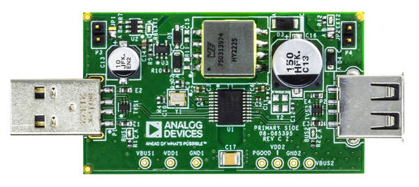
The EVAL-CN0550-EBZ is a 4-layer printed circuit board (PCB)
that allows evaluation of the CN0550 High Speed USB 2.0
Peripheral Isolator circuit. The board is fabricated with a 0.5oz./1oz.
copper cladding and IPC-4101 (or IPC-4103) laminates and bonding materials.
Designed to be connected between a host controller and a USB peripheral device, the EVAL-CN0550-EBZ features a small form-factor with dimensions of 2.315in ×1.335in x 0.062mm (PCB only). The evaluation board uses standard Type-A USB connectors for its signal path — for easy integration with USB systems, a male connector is used for the host side and a female connector is used for the peripheral side. Straight headers on each side allow the users to use an external power supply for high current applications.
Evaluation Board Hardware
USB Host Plug and LED Indicator (P1, BUS1)
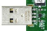
The USB host controller must be connected to the male USB-A connector (P1).
The yellow-green LED (BUS1) lights up to indicate the presence of 5V power from the USB host.
USB Peripheral Port and LED Indicator (P2, BUS2)
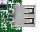
The USB peripheral device must be connected to the female USB-A connector (P2).
The yellow-green LED (BUS2) lights up to indicate the presence of 5V power for the USB peripheral device.
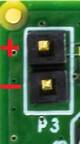
Host Side Power Connector and LED Indicator (P3, EXT1)
The onboard regulator circuit of the CN0550 can typically supply a maximum current of 440mA to the peripheral side when powered from the VCC pin of the USB host. For applications that require higher current, the CN0550 output can be increased by moving the J1 solder jumper to the ‘B’ position, and connecting an external >5VDC power supply across the P3 header.
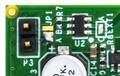
The red LED (EXT1) lights up to indicate the presence of an external DC power supply.
JP1 Position |
Power Source for the Onboard Regulator |
|---|---|
A |
VCC pin of USB host (Default). |
B |
External power supply connected across P3. |
Tip
The maximum voltage that can be safely applied at P3 is 32 V. Connect the (+) and (-) pins of the external power supply respectively to pins 1 and 2 of P3.
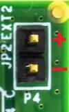
Peripheral Side Power Connector and LED Indicator (P4, EXT2)
For applications where 5V power is already available on the peripheral side, the onboard regulator can be bypassed by moving the J2 solder jumper to the ‘B’ position, and connecting the external 5V peripheral power across the P3 header.
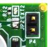
The red LED (EXT2) lights up to indicate the presence of an external DC power supply.
JP2 Position |
5 V Power Source for the Peripheral Side |
|---|---|
A |
Onboard regulator circuit (Default) |
B |
External power supply connected across P4 |
Tip
The voltage applied at P3 should be limited to the normal operating VCC range for USB (4.75V to 5.25V). Connect the (+) and (-) pins of the external power supply respectively to pins 1 and 2 of P4.
Schematic, Layout and Bill of Materials
Download
EVAL-CN0550-EBZ Design & Integration Files
Schematic
Bill of Materials
Gerber Files
Allegro Layout Files
Assembly Drawing