AD-M2KBNC-EBZ
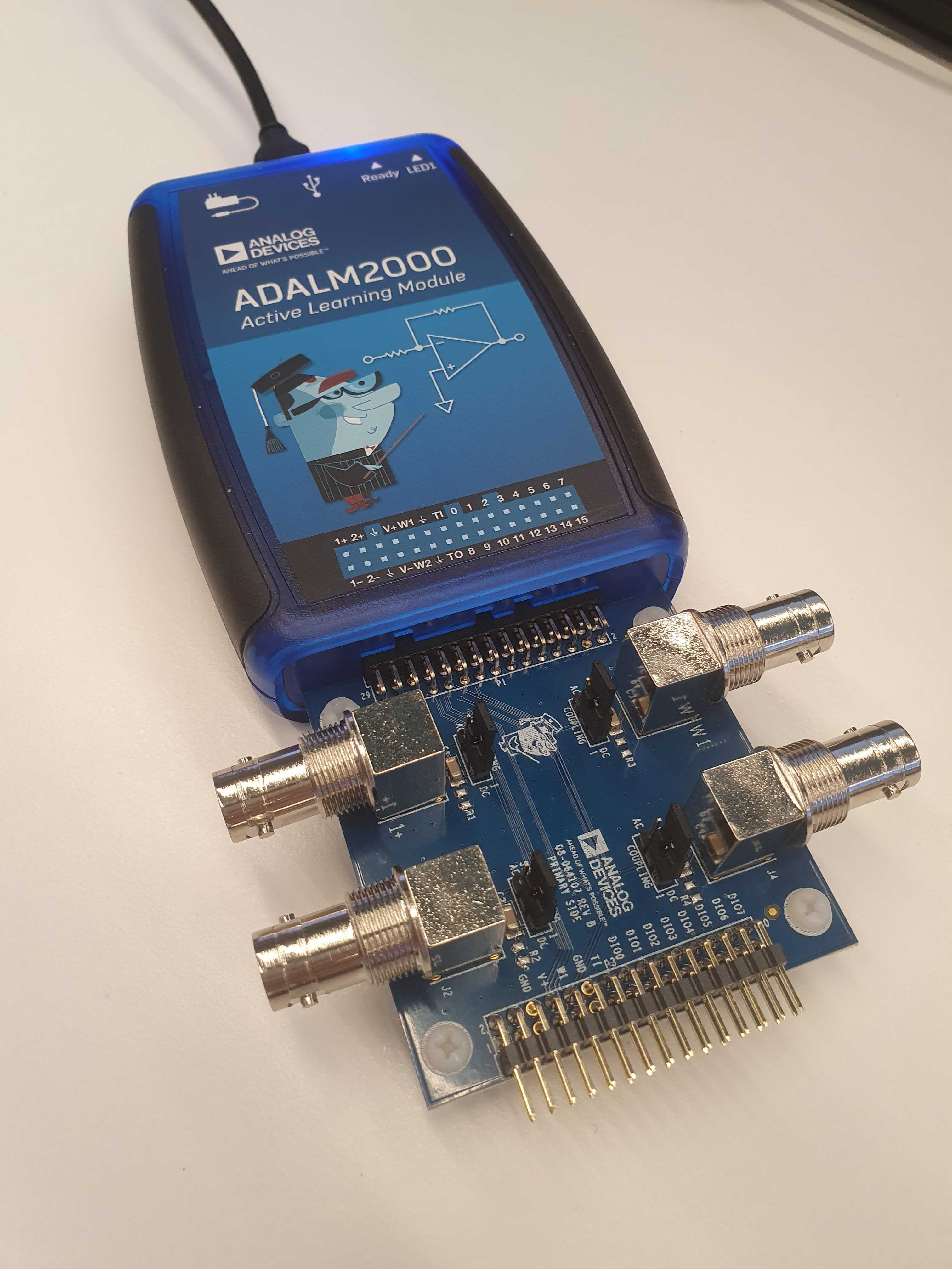
ADALM2000 BNC Adapter Board.
The AD-M2KBNC-EBZ is an ADALM2000 add-on board which allows the user to connect oscilloscope probes and other test leads to the analog inputs of M2K.
Features
AC or DC coupling on all channels
Possibility to reconfigure the analog inputs as differential input channels
Access to all other ADALM2000 output pins
Oscilloscope probes, BNC to grabber cables and mini grabber test clips are included in the package
Description
The AD-M2KBNC-EBZ has 2 single ended input channels and 2 single ended output channels. All these channels are terminated in a right-angle BNC connector which provides quick connection and a locking mechanism. The single ended input channels can be reconfigured as differential input channels by modifying a solder jumper on the bottom of the board. In this way, all 4 BNC connectors will be used for the analog input section and the output of the M2K is still available on the 30-pin header of the board.
Applications
Electronic test and measurement equipment
General-purpose signal processing applications
Automated test equipment
Educational applications
Package contents
AD-M2KBNC-EBZ
2x Oscilloscope Probes (PA360 60MHz x1 & x10 Passive Probe)
2x BNC to grabber cables
10x mini grabber test clips
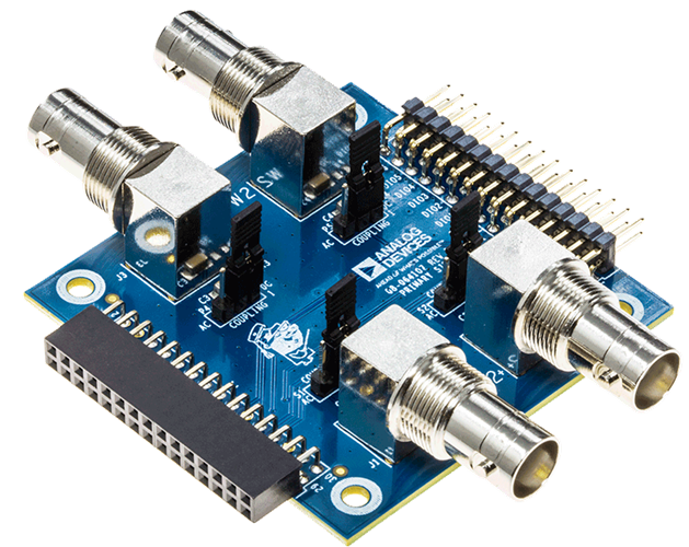

Getting Started
The BNC adapter board is simply plugged into the ADALM2000 and can be used straight away. It does not need any supply or additional circuitry.
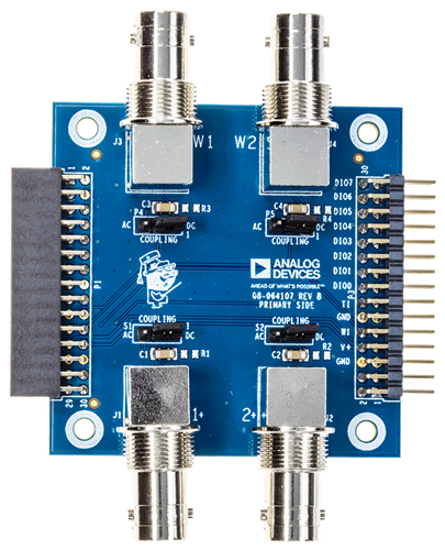
AC/DC Coupling
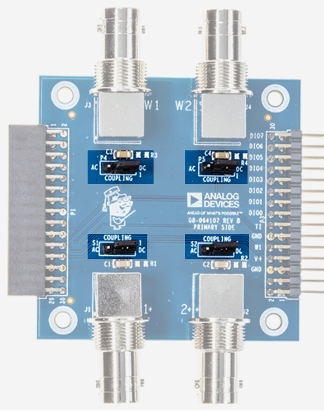
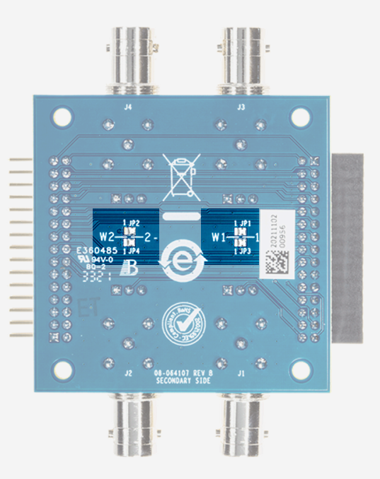
Figure 4. AD-M2KBNC-EBZ jumpers for AC/DC coupling
The input and output channels of this board can be AC or DC coupled using the shunt jumpers. In the following table is presented the jumper configuration:
Jumper |
Missing |
Jumper 1-2 shorted |
Jumper 2-3 shorted |
|---|---|---|---|
S1- Analog In channel 1 |
inoperable /disconnected |
DC coupled |
AC Coupled |
S2- Analog In channel 2 |
inoperable /disconnected |
DC coupled |
AC Coupled |
P4- Analog Out channel 1 |
inoperable /disconnected |
DC coupled |
AC Coupled |
P5- Analog Out channel 2 |
inoperable /disconnected |
DC coupled |
AC Coupled |
Differential Inputs
The AD-M2KBNC-EBZ inputs are reconfigurable. By default 1+ and 2+ channels are referenced to the GND of the board and are single ended input channels. There are some solder jumpers on the bottom of the board that allow the user to change the default configuration and use the differential inputs, as ADALM2000 allows this. If the jumpers are soldered as in the table below, the BNC connectors J3 and J4 correspond to channels 1- and 2- of the ADALM2000.
Solder jumpers Shorted Pins |
BNC Connector to M2K Pin Correspondence |
||||||
|---|---|---|---|---|---|---|---|
JP1 |
JP2 |
JP3 |
JP4 |
J1 |
J2 |
J3 |
J4 |
1 2 |
1 2 |
1 2 |
1 2 |
1+ |
2+ |
W1 |
W2 |
2 3 |
2 3 |
2 3 |
2 3 |
1+ |
2+ |
1- |
2- |