No-OS User Guide
This user guide uses no-OS's documentation and supports the carriers NUCLEO-H503RB and NUCLEO-H563ZI. For linux, see Linux User Guide,
Building the firmware
For no-OS:
Follow the no-OS build guide to set up your development environment and build the firmware for the AD405X project.
For Linux:
Follow the Kuiper Linux documentation to prepare an SD card with the latest Kuiper image. The AD4062 Linux driver and devicetree are included in recent Kuiper releases.
Hardware setup
Before writing the no-OS firmware, set up the hardware with following steps:
Disconnect both the evaluation board and the carrier from all power sources.
Connect the evaluation board to the carrier using the Arduino Uno compatible headers (there is only one position where all pins are connected).
Check jumpers and powering on instructions specific for the carrier.
When powering the evaluation board from the carrier, follow:
Set JP2 jumper on the evaluation board to the +5V position. This position connects the evaluation board power management circuitry to the +5 V pin on the Arduino Uno power header.
Connect the carrier to a PC with a USB cable, the evaluation board DS1 LED should turn on, as well as other LEDs on the carrier.
When powering the evaluation board from an external power supply, follow:
Set JP2 jumper on the evaluation board to the VIN position. This position connects the evaluation board power management circuitry to the VIN pin on the Arduino Uno power header.
Power on the carrier via the external power supply option (in general, via a DC jack), the evaluation board DS1 LED should turn on, as well as other LEDs on the carrier.
Connect the carrier to a PC with a USB cable.
I3C Address Configuration
The AD4060/AD4062 include three digital input pins ADDR0, ADDR1, and ADDR2. The ADDR[2:0] pins enable the assignment of up to eight unique part instance values to support up to eight AD4060/AD4062s on one I3C bus.
The evaluation board’s jumpers JP11, JP12, and JP10 allow for setting the ADDR0, ADDR1, and ADDR2 respectively to either VIO or GND.
Flashing the firmware
These steps are done after the hardware setup, with the board powered on and connected to a PC.
Build the no-OS firmware following the build guide. The AD405X project supports multiple examples:
basic_i3c_example: Interactive example for I3C devices that prints samples and waits for threshold events
i3c_dma_example: I3C example with DMA support
iio_example: TinyIIO server for use with libiio clients
See AD405X no-OS Example Project STM32 for detailed build and flash instructions. Flash the built .elf file to the STM32 board using STM32 Cube IDE or by copying to the USB mass storage device.
Quick start
Connect a precision signal source or signal generator to the analog input Subminiature Version A (SMA) connectors to drive the AD4060/AD4062 inputs into their specified operating ranges.
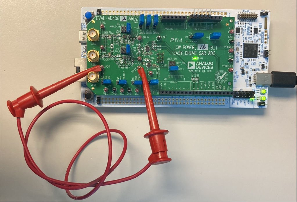
Figure 1 Biasing the EVAL-AD4062-ARDZ Inputs Without Signal Generator Hardware for Software Validation
If no signal generator is available, a jumper cable between the VREF and VCM test points can be used to bias the AD4060/ AD4062 analog inputs to VREF. This is preferred over connecting the amplifier inputs to GND, because the amplifier VEE rails are connected to GND by default.
Evaluation board hardware
The evaluation board includes the AD4060/AD4062 with companion circuitry for an out-of-the-box evaluation experience:
ADC: AD4060BCPZ/AD4062BCPZ (14-lead LFCSP)
Voltage reference: MAX6070 2.5V low-noise reference
Amplifiers: Two MAX44260 low-power, rail-to-rail op amps
Power regulator: ADP7118 3.3V LDO regulator
Digital Interface
The AD4060/AD4062 digital interface includes:
I3C bus: For reading and writing data (SDA and SCL on Arduino headers)
GP0/GP1: Two programmable GPIOs with multiple functions:
Data Ready (RDY) signal
Threshold interrupt (GP_INTR)
Device enable (DEV_EN) for AFE power cycling
Static high/low outputs
GPIO controller functionality (Linux only)
EEPROM: On-board I2C EEPROM for board identification
Power Domains
The evaluation board operates on the following power domains:
Power Rail |
Source |
Default Voltage |
|---|---|---|
+5V/VIN |
Arduino header (from carrier) |
5V |
VSUPPLY |
ADP7118 LDO regulator |
3.3V |
VDD |
VSUPPLY (via JP8) |
3.3V |
VIO |
IOREF from carrier (via JP1) |
3.3V |
VREF |
MAX6070 reference |
2.5V |
For more detailed hardware information, see the EVAL-AD4060/AD4062 User Guide.
Interfacing with TinyIIO
The no-OS driver supports the AD4060/AD4062 I3C devices through a core driver and a TinyIIO layer. The TinyIIO layer exposes the device to Libiio clients running on a host PC over a serial connection.
For language bindings and high level GUI tools see Libraries and GUI Tools.
Connecting to the device
Execute on the host PC to list the device:
~$
iio_info -u serial:/dev/ttyACM0,115200,8n1
This will display the IIO device information, available channels and attributes.
Available channels
The no-OS TinyIIO implementation exposes two channels:
voltage_adc_mode (channel 0): Standard ADC mode, single sample per conversion
voltage_burst_averaging_mode (channel 1): Burst averaging mode with oversampling
Channel attributes
Each channel provides the following attributes:
raw: Read the raw ADC value (integer)
sample_rate: Configure the internal sample rate in Hz (read/write)
avg_filter_length: Configure the averaging filter length for burst mode (read/write)
Reading a single sample
To read a single sample from the ADC mode channel:
~$
iio_attr -u serial:/dev/ttyACM0,115200,8n1 -c ad4062 voltage_adc_mode raw
To read from the burst averaging mode channel:
~$
iio_attr -u serial:/dev/ttyACM0,115200,8n1 -c ad4062 voltage_burst_averaging_mode raw
Configuring sample rate
View the current sample rate:
~$
iio_attr -u serial:/dev/ttyACM0,115200,8n1 -c ad4062 voltage_adc_mode sample_rate
Set a new sample rate (in Hz):
~$
iio_attr -u serial:/dev/ttyACM0,115200,8n1 -c ad4062 voltage_adc_mode sample_rate 1000000
Available sample rates: 2000000, 1000000, 333000, 100000, 33000, 10000, 3000, 1000, 500, 333, 250, 200, 166, 140, 125, 111 Hz.
Configuring averaging
For burst averaging mode, configure the filter length:
~$
iio_attr -u serial:/dev/ttyACM0,115200,8n1 -c ad4062 voltage_burst_averaging_mode avg_filter_length 8
Capturing buffered data
To capture a stream of samples to a buffer:
~$
iio_readdev -u serial:/dev/ttyACM0,115200,8n1 -s 1024 -b 256 ad4062 voltage_adc_mode > data.bin
This captures 1024 samples in buffers of 256 samples each.
tinyIIO limitations
Not all driver features are exposed through tinyIIO, in particular, threshold events are not available as IIO events like in the linux driver, still, an example that demos threshold events without tinyIIO is provided.